EM78P312N
8-Bit Microcontroller
34 •
Product Specification (V1.0) 10.03.2006
(This specification is subject to change without further notice)
SPI S
RBF
WBE
SPI F
read data
shift start shift start
/SCK pin
SI pi n
c0 c1 c2 c3 c4 c5 c6 c7
a
SPI D
d0 d1 d2 d3 d4 d5 d6 d7
read dat a
d
shift finish
SO pi n
a0 a1 a2 a3 a4 a5 a6 a7
b0 b1 b2 b3 b4 b5 b6 b7
shift finish
c
write data
b
write data
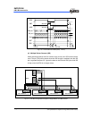
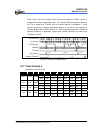
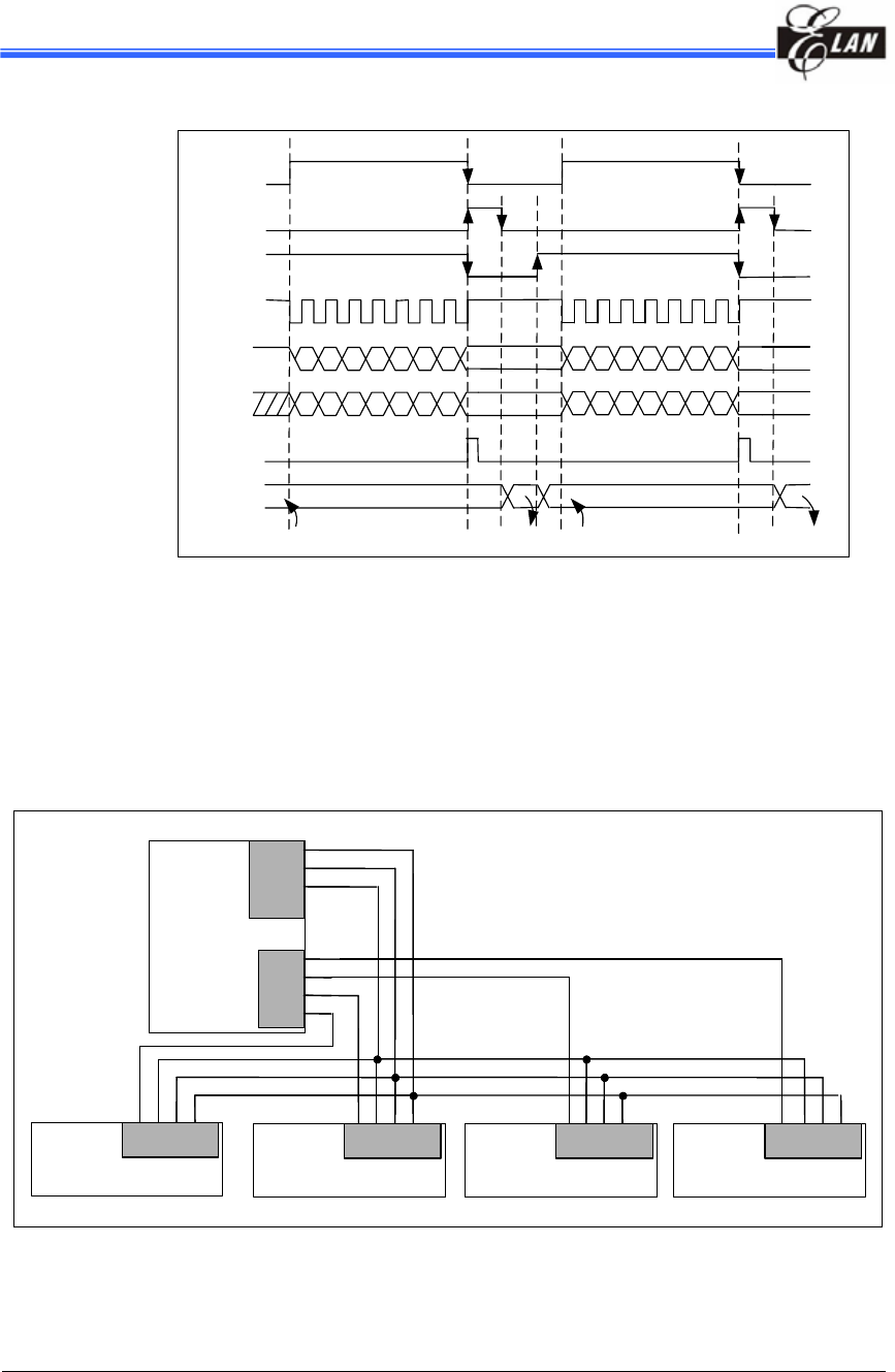
Fig. 5-16 Transmit/Receive Mode (8-bit, 1 word)
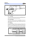
(d) Multiple Device Connect (/SS)
When selecting external clock for transfer clock source, the /SS function can be
used. This pin (/SS) will be active when the /SS function is enabled, else the /SS
pin is a general purpose I/O. Ignore the data on the SDI and SDO pins while /SS
is high, since the SDO is no longer driven.
Master
SDI
P.67
P 65
P 64
SDO
SDI
SCK
/SS
Master
SDI
SDO
SCK
/SS
Slave Device 1
P67
P66
P65
P64
SDI
SDI
SDO
SCK
/SS
Slave Device 2
SDI
SDI
SDO
SCK
/SS
Slave Device 3
SDI
SDI
SDO
SCK
/SS
Slave Device 4
Fig. 5-17 The SPI Configuration Example of Single-Master and Multi-Slaves


