


EM78P312N
8-Bit Microcontroller
16 •
Product Specification (V1.0) 10.03.2006
(This specification is subject to change without further notice)
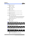
Bit 6 ( EVEN ) : Select parity check
EVEN = “0” : Odd parity
EVEN = “1” : Even parity
Bit 5 ( PRE ) : Enable parity addition
PRE = “0” : Disable
PRE = “1” : Enable
Bit 4 ( PRERR ) : Parity error flag.
Set to 1 when parity error occurred, and cleared to 0 by software.
Bit 3 ( OVERR ) : Overrun error flag.
Set to 1 when overrun error occurred, and cleared to 0 by software.
Bit 2 ( FMERR ) : Framing error flag.
Set to 1 when framing error occurred, and cleared to 0 by software.
Bit 1 ( URBF ) : UART read buffer full flag.
Set to 1 when one character is received. Reset to 0 automatically when read
from the URS register. URBF will be cleared by hardware when receiving is
enabled. URBF bit is read-only. Therefore, reading the URS register is
necessary to avoid an overrun error.
Bit 0 ( RXE ) : Enable receiving
RXE = “0” : Disable
RXE = “1” : Enable
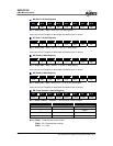
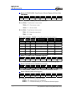
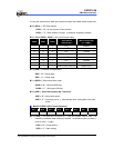
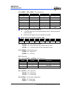
Bank 2 R8 URRD (UART Receive Data Buffer)
Bit 7 Bit 6 Bit 5 Bit 4 Bit 3 Bit 2 Bit 1 Bit 0
URRD7 URRD6 URRD5 URRD4 URRD3 URRD2 URRD1 URRD0
Bit 7 ~ Bit 0 ( URRD7 ~ URRD0 ) : UART receive data buffer. Read only.
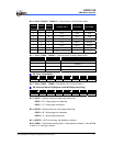
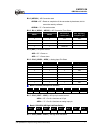
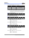
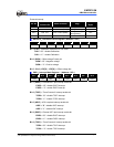
Bank 2 R9 URTD (UART Transmit Data Buffer)
Bit 7 Bit 6 Bit 5 Bit 4 Bit 3 Bit 2 Bit 1 Bit 0
URTD 7 URTD 6 URTD 5 URTD 4 URTD 3 URTD 2 URTD 1 URTD0
Bit 7 ~ Bit 0 ( URTD 7 ~ URTD 0) : UART transmit data buffer. Write only.
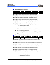
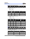
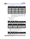
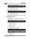
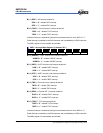
Bank 3 R5 SPIC1 (SPI Control Register 1)
Bit 7 Bit 6 Bit 5 Bit 4 Bit 3 Bit 2 Bit 1 Bit 0
SMP DCOL BRS2 BRS1 BRS0 EDS DORD WBE
Bit 7 ( SMP ) : SPI data input sample phase.
SMP = “0” : Input data sampled at middle of data output time
SMP = “1” : Input data sampled at the end of data output time