


EM78P312N
8-Bit Microcontroller
54
• Product Specification (V1.0) 10.03.2006
(This specification is subject to change without further notice)
Bit 4 (OSC) : Oscillator type selection
OSC = “0” : RC type
OSC = “1” : Crystal type
Bit 3 (HLP) : Power selection
HLP = “0” : Low power
HLP = “1” : High power
Bit 2~0 (PR2~PR0) : Protect Bit
PR2~PR0 are write-protect bits, configured as follow s:
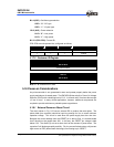
PR2 PR1 PR0 Protect
Others Enable
1 1 1 Disable
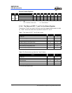
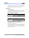
5.17.2 Customer ID Register
Word 1
Bit 12~Bit 0
XXXXXXXXXXXXX
Word 2
Bit 12~Bit 0
XXXXXXXXXXXXX
Bits 12 ~ 0: Customer’s ID code
5.18 Power-on Considerations
Any microcontroller is not guaranteed to start and operate properly before the power
supply maintains at its steady state. The EM78P312N has a built-in Power On Voltage
Detector (POVD) with a detecting level of 2.1V. It will work well if V
DD rises fast enough
(10 ms or less). In many critical applications, however, additional components are
required to provide solutions on probable power-up problems.
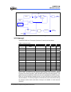
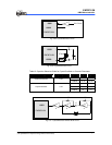
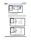
5.18.1 External Power-on Reset Circuit
The circuit shown in Fig. 5-33 use an external RC to produce the reset pulse. The
pulse width (time constant) should be kept long enough for V
DD to reach minimum
operation voltage. This circuit is used when the power supply has slow rise time.
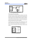
Because the current leakage from the /RESET pin is about
±5μA, it is recommended
that R should not be greater than 40K. In this way, the /RESET pin voltage is held
below 0.2V. The diode (D) acts as a short circuit at the moment of power down. The
capacitor C will discharge rapidly and fully. Rin, the current-limited resistor, will prevent
high current or ESD (electrostatic discharge) from flowing to pin /RESET.