


EM78P312N
8-Bit Microcontroller
Product Specification
(V1.0) 10.03.2006 • 53
(This specification is subject to change without further notice)
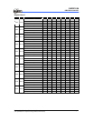
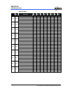
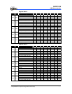
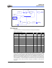
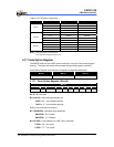
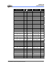
Table13. RC Oscillator Frequencies
Cext Rext Average Fosc 5V, 25°C Average Fosc 3V, 25°C
3.3k 4.32 MHz 3.56 MHz
5.1k 2.83 MHz 2.8 MHz
10k 1.62 MHz 1.57 MHz
20 pF
100k 184kHz 187kHz
3.3k 1.39 MHz 1.35 MHz
5.1k 950kHz 930kHz
10k 500kHz 490kHz
100 pF
100k 54kHz 55kHz
3.3k 580kHz 550kHz
5.1k 390kHz 380kHz
10k 200kHz 200kHz
300 pF
100k 21kHz 21kHz
Note:
1
: Measured based on DIP packages.
2
: The values are for design reference only.
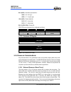
5.17 Code Option Register
The EM78P312N has one CODE option word that is not part of the normal program
memory. The option bits cannot be accessed during normal program execution.
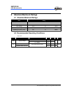
Code Option Register and Customer ID Register arrangement distribution:
Word 0 Word 1 Word 2
Bit 12~Bit 0 Bit 12~Bit 0 Bit 12~Bit 0
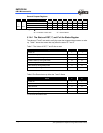
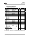
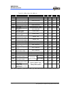
5.17.1 Code Option Register (Word 0)
Word 0
Bit 12 ~ 9 Bit 8 Bit 7 Bit 6 Bit 5 Bit 4 Bit 3 Bit 2 Bit 1 Bit 0
- CLKS ENWDTB CYES - OSC HLP PR2 PR1 PR0
Bit 12 ~ 9 : Not used
Bit 8 (CLKS) : Instruction period option bit
CLKS = “0” : two oscillator periods
CLKS = “1” : four oscillator periods.
Refer to the Instruction Set section.
Bit 7 (ENWDTB) : Watchdog timer enable bit
ENWDTB = “0” : Enable
ENWDTB = “1” : Disable
Bit 6 (CYES) : Cycle selection for JMP, CALL instruction
CYES = “0” : One cycle
CYES = “1” : Two cycles