


EM78P312N
8-Bit Microcontroller
Product Specification (V1.0) 10.03.2006
• 29
(This specification is subject to change without further notice)
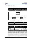
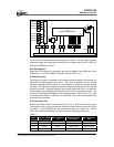
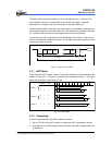
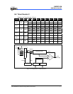
The figure below shows the general format of one character sent or received. The
communication channel is normally held in the marked state (high). Character
transmission or reception starts with a transition to the space state (low).
The first bit transmitted or received is the start bit (low). It is followed by the data bits, in
which the least significant bit (LSB) comes first. The data bits are followed by the parity
bit. If present, then the stop bit or bits (high) confirm the end of the frame.
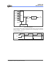
In receiving, the UART synchronizes on the falling edge of the start bit. When two or
three “0” are detected during three samples, it is recognized as normal start bit and the
receiving operation is started.
START
bit
D0 D1 D2 Dn
Parity
bit
STOP
bit
1 bit 7 or 8 bits
One character or frame
1 bit 1 bits
Idle state
(mark)
I
Fig. 5-11 Data Format in UART
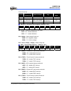
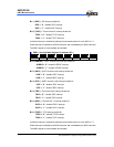
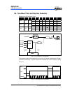
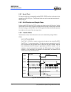
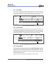
5.7.1 UART Mode
There are three UART modes. Mode 1 (7 bits data) and Mode 2 (8 bits data) allow the
addition of a parity bit. The parity bit addition is not available in Mode 3. The Figure
below shows the data format in each mode.
UMODE PRE
0 0 0
0 0 1
0 1 0
0 1 1
1 0 X
12345 11109876
START
STOP
7 bits DATA
START
STOP
7 bits DATA Parity
START
STOP
8 bits DATA
START
STOP
8 bits DATA Parity
START
STOP
9 bits DATA
Mode 1
Mode 3
Mode 2
Fig. 5-12 UART Mode
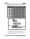
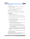
5.7.2 Transmitting
In transmitting serial data, the UART operates as follows:
1. Set the TXE bit of the URC1 register to enable the UART transmission function.
2. Write data into the URTD register and the UTBE bit of the URC1 register will be set
by hardware.