EM78P312N
8-Bit Microcontroller
10 •
Product Specification (V1.0) 10.03.2006
(This specification is subject to change without further notice)
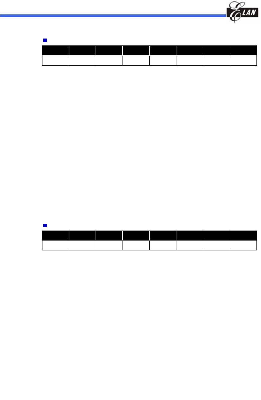
RE (Interrupt Status Flag Register 1)
Bit 7 Bit 6 Bit 5 Bit 4 Bit 3 Bit 2 Bit 1 Bit 0
EXIF5 TCIF2 ADIF 0 EXIF3 TCIF4 SPIF TCIF3
Bit 7 ( EXIF5 ) : External Interrupt Flag (/INT5), flag cleared by software.
Bit 6 ( TCIF2 ) : 16-bit Timer/Counter 2 Interrupt Flag, flag cleared by software.
Bit 5 ( ADIF ) : AD conversion complete flag, flag cleared by software.
Bit 3 ( EXIF3 ) : External Interrupt Flag (/INT3), flag cleared by software.
Bit 2 ( TCIF4 ) : 8-bit Timer/Counter 4 Interrupt Flag, flag cleared by software.
Bit 1 ( SPIF ) : SPI Mode Interrupt Flag, flag cleared by software.
Bit 0 ( TCIF3 ) : 8-bit Timer/Counter 3 interrupt flag, flag cleared by software.
0 : means no interrupt request
1 : means with interrupt request
z ISFR1 can be cleared by instruction, but cannot be set by instruction
z IMR1 is the interrupt mask register
z Note that reading ISFR1 will obtain the result of the ISFR1 "logic AND" and
IMR1.
RF(Interrupt Status Flag Register 2)
Bit 7 Bit 6 Bit 5 Bit 4 Bit 3 Bit 2 Bit 1 Bit 0
0 UERRIF RBFF TBEF TBIF EXIF1 0 TCIF0
Bit 6 (UERRIF) : UART Receiving Error Interrupt, cleared by software or UART
disabled.
Bit 5 (RBFF) : UART Receive Mode Data Buffer Full Interrupt Flag. Flag cleared by
software.
Bit 4 (TBEF) : UART Transmit Mode Data Buffer Empty Interrupt Flag. Flag cleared by
software.
Bit 3 (TBIF) : Time Base Timer Interrupt Flag. Flag cleared by software.
Bit 2 (EXIF1) : External Interrupt Flag (INT1). Flag cleared by software.
Bit 0 (TCIF0) : TCC Overflow Interrupt Flag. Set as TCC overflows; flag cleared by
software.
0 : means no interrupt request
1 : means with interrupt request


