


EM78P312N
8-Bit Microcontroller
Product Specification (V1.0) 10.03.2006
• 39
(This specification is subject to change without further notice)
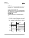
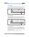
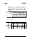
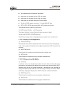
of the TC3 pin input, the contents of the counter are loaded into TCR3A, counter is
cleared and interrupt is generated again. If an overflow before the edge is detected,
the FFH is loaded into TCR3DA and an overflow interrupt is generated. During
interrupt processing, it can be determined whether or not there is an overflow by
checking whether the TCR3DA value is FFH. After an interrupt (capture to TCR3DA or
overflow detection) is generated, capture and overflow detection are halted until
TCR3DA is read out.
K-2 K-1 K
0
1
m-1 m m+1 n-1 n
0
1 2 3 FE FF0 123
Source Clock
Up-counter
TC3 Pin Input
TCR3DA
TCR3DB
TC3 Interrupt
Reading TCR3DA
K
m
n FF (Overflow)
FE
Capture Capture
Overflow
Fig. 5-23 Timing Chart of Capture Mode
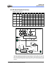
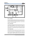
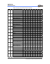
5.11 Timer/Counter 4
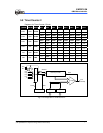
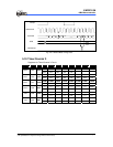
Registers for Timer 4 Circuit
R_BANK Address Name Bit 7 Bit 6 Bit 5 Bit 4 Bit 3 Bit 2 Bit 1 Bit 0
TC4FF1 TC4FF0 TC4S TC4CK2 TC4CK1 TC4CK0 TC4M1 TC4M0
Bank 0 0X0B TC4CR
R/W R/W R/W R/W R/W R/W R/W R/W
TC4D7 TC4D6 TC4D5 TC4D4 TC4D3 TC4D2 TC4D1 TC4D0
Bank 0 0X0C TC4D
R/W R/W R/W R/W R/W R/W R/W R/W
EXIF5 TCIF2 ADIF 0 EXIF3 TCIF4 SPIF TCIF3
Bank 0 0x0E ISFR1
R/W R/W R/W -- R/W R/W R/W R/W
EXIE5 TCIE2 ADIE 0 EXIE3 TCIE4 SPIE TCIE3
SFR 0x0E IMR1
R/W R/W R/W -- R/W R/W R/W R/W