


EM78P312N
8-Bit Microcontroller
26 •
Product Specification (V1.0) 10.03.2006
(This specification is subject to change without further notice)
5.6 Time Base Timer and Keytone Generator
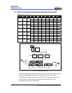
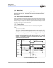
Registers for AD Converter Circuit
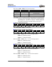
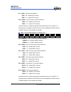
R_BANK Address Name Bit 7 Bit 6 Bit 5 Bit 4 Bit 3 Bit 2 Bit 1 Bit 0
TEN TCK1 TCK0 0 TBTEN TBTCK2 TBTCK1 TBTCK0
Bank 1 0X0E TBKTC
R/W R/W R/W -- R/W R/W R/W R/W
0 UERRIF RBFF TBEF TBIF EXIF1 0 TCIF0
Bank 0 0x0F ISFR2
0 R/W R/W R/W R/W R/W 0 R/W
0 UERRIE URIE UTIE TBIE EXIE1 0 TCIE0
SPR 0x0F IMR2
0 R/W R/W R/W R/W R/W 0 R/W
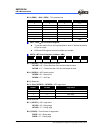
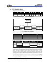
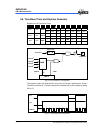
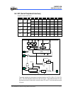
MUX
Fosc/2
Fosc/2
Fosc/2
Fosc/2
13
12
11
10
TBKTC
TCK1:0
2
/TONE Pin
TEN
D Q
Output Latch
Data Output
Output Enable (P63)
Fig. 5-6 Tone Output Pin Configuration
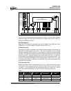
The Keytone output can generate 50% duty pulse for driving a piezo-electric buzzer.
The P63 must be set to “1” before the keytone is enabled and it can be halted by setting
P63 to “0”.
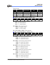
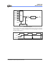
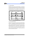
P63
TEN
TONE Pin
Fig. 5-7 Tone Output Pin Timing Chart