


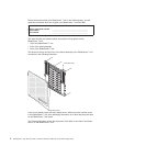

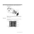
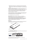
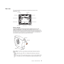
System service cards
These cards contain system service instructions and a writable area for your use.
The cards are located in a slot just above the management-module bays. To access
the service cards, slide out the cards as shown in the following illustration.
C
MM
1
C
M
M
2
ES
D
System service card
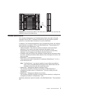
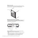
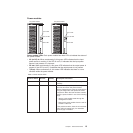
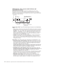
Management module controls and indicators
These management-module controls and indicators provide status information about
the management module and remote management connection. For additional
information, see the Hardware Maintenance Manual and Troubleshooting Guide on
the IBM BladeCenter T Documentation CD.
Power LED
Active LED
Error LED
Management module
Reset button
Serial port
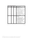
Management module LEDs: These LEDs provide status information about the
management module and remote management connection.
v Power: When this green LED is lit, it indicates that the management module has
power.
v Active: When this green LED is lit, it indicates that the management module is
actively controlling the BladeCenter T unit. Only one management module
actively controls the BladeCenter T unit. If two management modules are
installed in the BladeCenter T unit, this LED is lit on only one.
10 BladeCenter T Type 8720 and 8730: Hardware Maintenance Manual and Troubleshooting Guide