


must be installed in the BladeCenter T unit in I/O-module bay 1 or 2, or both,
before the integrated Ethernet controllers on each blade server system board
can be used.
The Ethernet controllers are integrated on each blade server system board. The
Ethernet controllers provide 1-Gbps full-duplex capability only, which enables
simultaneous transmission and reception of data to the external ports on the
Ethernet switches. You do not need to set any jumpers or configure the controller
for the blade server operating system. However, you must install a device driver on
the blade server to enable the blade server operating system to address the
Ethernet controller. For blade server device drivers and information about
configuring the Ethernet controllers, see the Ethernet software CD that comes with
your blade server.
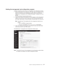
BladeCenter T networking guidelines
Your networking administrator should assist in the configuration of the network
infrastructure before you connect the BladeCenter T unit to a LAN switch or similar
network device. This section provides additional guidelines that might be useful in
setting up your system.
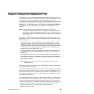
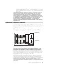
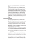
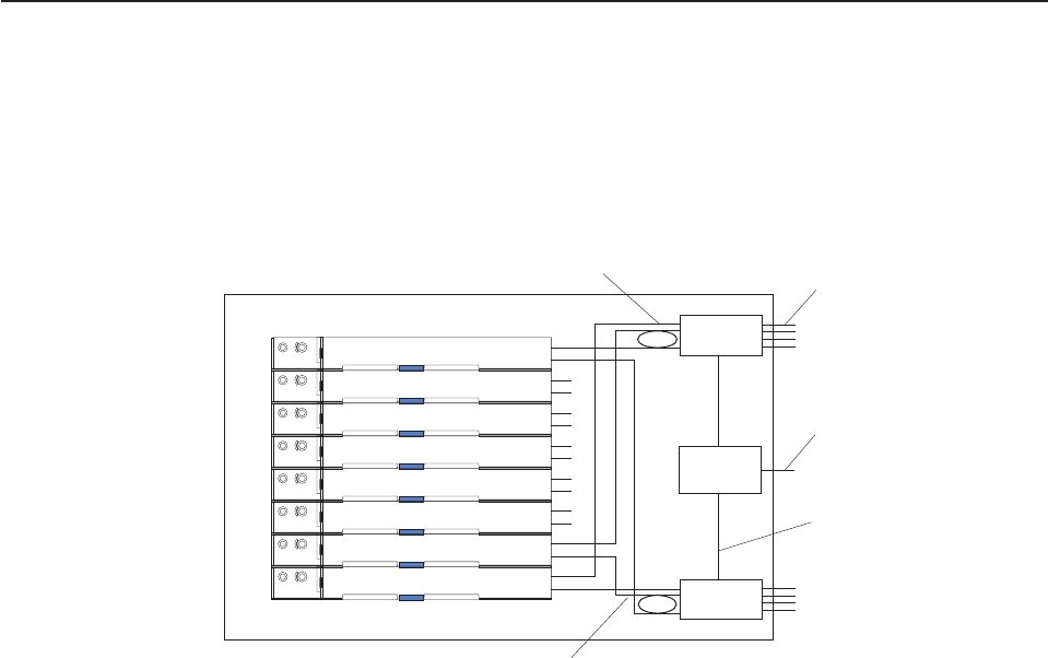
A BladeCenter T unit with two Ethernet switch modules and one management
module has the internal configuration that is shown in the following illustration:
MAC
1a
1b
2a
2b
3a
3b
4a
4b
5a
5b
6a
6b
7a
7b
8a
8b
1
2
3
4
5
6
7
8
Switch A
Mgmt
Mod
Switch B
100 Mbps links
10/100 Mbps
1 Gbps or
100 Mbps links
1 Gbps links
1 Gbps links
Note: 2nd switch module is optional
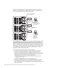
Each blade server has two independent Ethernet controllers, each with its own
MAC address and a dedicated 1 Gbps link to one of the switch modules in I/O
module bays 1 and 2 (controller 1 to switch A and controller 2 to switch B in the
illustration). In this configuration (the default), the blade servers share access to
four external ports on each switch. There is no internal data path between the two
switches within the BladeCenter T unit; an external network device is required for
data packets to flow from one internal switch to the other.
The management module has a separate internal 100 Mbps link to each switch.
These links are for internal management and control only. No data packets are
allowed to flow from application programs on the blade servers to the management
module over this path. A separate, nonswitched path (not shown) is used for
communication between the management module and a service processor on each
blade server.
Chapter 2. Configuring the BladeCenter T unit 31