


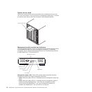
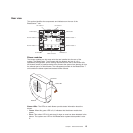
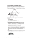

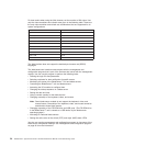
LAN-module indicators and input/output connectors
The LAN module is a hot-swap module that is installed on the rear of the
BladeCenter T unit and is held in place by captive thumbscrews. The LAN module
provides the electrical and mechanical interface to the BladeCenter T unit for the
two local area network (Ethernet) connections, as driven from each management
module, and the telco external alarms. This module contains two RJ-45 connectors
with LEDs and one DSUB 15P telco alarm connector.
2
Alarms
1
Ethernet link LED
Ethernet activity LED
Alarms connector
Remote management
and console (Ethernet)
Thumbscrews
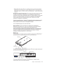
LAN-module LEDs: These LEDs provide status information about the LAN
connection:
v Ethernet link: When this green LED is lit, there is an active connection through
the port to the network.
v
Ethernet activity: When this green LED is flashing, it indicates that there is
activity through the port over the network link.
LAN-module
connectors:
v Remote management and console (Ethernet) connectors: The LAN module
provides two Ethernet RJ-45 connectors.
The BladeCenter T LAN module contains two 10/100 Mb Ethernet connectors
that provide the remote connections, driven from each management module, to
the network management station on the network.
Use these ports for remote management and remote console.
The network management station, through these connectors, can access control
functions running in the management module, the service processor on each
blade server, or within each switch module. However, it cannot use these ports to
communicate with application programs running in the blade servers. The
network management station must direct those communications through a
network connected to the external ports in the I/O modules in the BladeCenter T
unit.
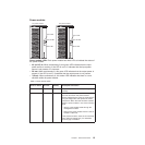
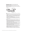
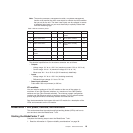
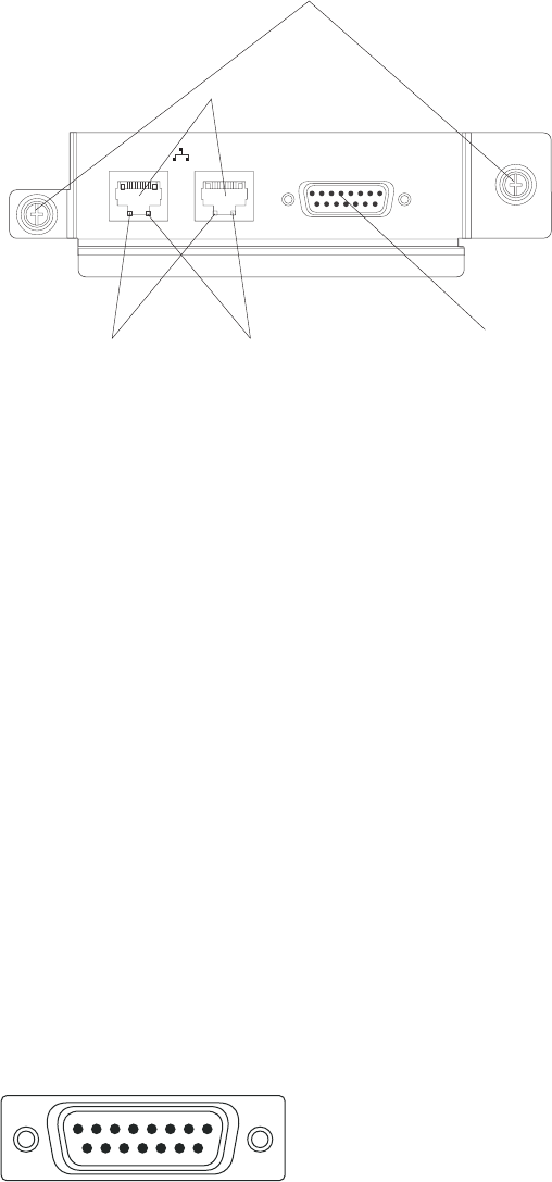
v Alarms connector: The LAN module provides one telco DB15 alarms connector
(male) for critical, major, and minor telco alarms. Each of the alarms has a relay
that enables multiple system alarm indicators to be daisy-chained together.
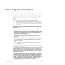
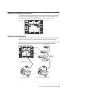
Table 4 on page 19 shows the pinouts for the telco alarms connector.
Alarms
18
915
18 BladeCenter T Type 8720 and 8730: Hardware Maintenance Manual and Troubleshooting Guide