


34 Theory of Operation
Croma24 Service Manual
2. Motor current sense
The voltage across a series current sense resistor is measured
and level shifted so that it is centered around 5 V.
3. Comparator
This portion divides the output of the reference waveform gen-
erator by two and compares it to the output of the motor current
sensor. Logic inside the gate array generates the control signals
for the power driver that applies voltage across the motor wind-
ing in order to make the actual current match the reference
waveform.
4. Power driver
An H-bridge allows the supply voltage to be applied across the
winding in either polarity to drive the current to the desired
value.
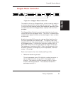
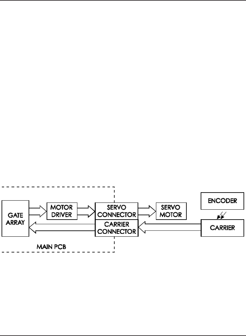
Servo Motor Controller
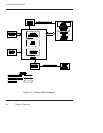
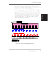
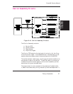
Figure 2-7. Servo Motor Controller.
The Carrier Assembly is driven by the Servo Motor. The speed of the
Carrier Assembly is controlled by varying the duty cycle of the power
applied to the controller. The microprocessor checks the position of
the Carrier Assembly approximately 1,000 times per second (during
the servo interrupt). It then updates the PWM (pulse width modula-