38 Theory of Operation
Croma24 Service Manual
also constantly monitors the media during printing to determine if
the media has run out.
If no paper is sensed, the paper sensor sends this information to the
MPCB, which immediately begins an ‘out of paper’ subroutine. This
subroutine starts the LEDS on the printer to blink (green blinks slow
while yellow blinks faster.) It also informs the host computer of the
situation and stops the printer from printing until more media is
loaded.
The sensor also checks for the size of the media loaded so it can
determine the proper printing parameters.
Power Supply
An internal UL recognized switching power module supplies power
for the Croma24 printer. It provides a constant 5 VDC and 24 VDC
output from input voltage in the range of 90-264 VAC. The 24 V
supply is used for: the stepper controller (which advances the
paper); the servo controller (which moves the Carrier); and power to
fire the inkjets. The 5V supplies power to the logic circuits.
The power supply is fused using a 2 A 250 V fast blow type fuse.
The outputs share a common ground which is isolated from earth
ground within the supply itself. Earth ground and DC ground are
connected external to the power supply.
The power supply will shut down under overload/short circuit condi-
tions on any output over the full range of input voltage. Overvoltage
protection is 20%-30% above nominal for the 5 V and 24 V outputs.
System Grounding
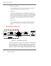
Due to the amount of plastics used in the manufacturing of the
printer, a system of grounding the metal assemblies to each other is
required. If no common ground was in place, the potential of electric
shock could exist due to static voltage buildup on the individual
assemblies. The system grounding network ensures that all metallic
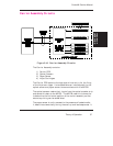
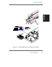
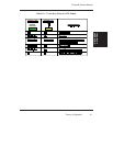
assemblies have the same ground potential. Figures 2-11 and 2-12
show how the ground straps are implemented on the printers.


