Assembly\Disassembly 93
ASSEMBLY/
DISASSEMBLY
Croma24 Service Manual
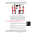
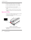
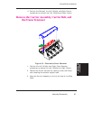
4. Move the Carrier Belt to the left so it is out of the way of the
Servo Motor pulley.
5. Move the Carrier Assembly to the left end of the Slide Shaft.
Integrated circuits may become weakened or dam-
aged by electrical discharge. Do not touch or work
near integrated circuits without wearing an ESD
wrist strap.
6. Put on an ESD wrist strap.
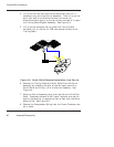
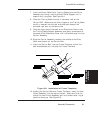
7. In order to have access to the back screw on the Servo Motor,
it is necessary to disconnect the Trailing Cable from the
MPCB and lift up the right end of the Trailing Cable.
Disconnect the Trailing Cable connector at the J6 location on
the MPCB.
8. Lift up gently and hold the right end of the Trailing Cable.
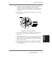
9. Using a #2 Phillips screwdriver, remove the back screw on the
Servo Motor. The screwdriver will be at a slight angle. Be
careful not to strip the head of the screw or to cause damage
to the Encoder Strip.
10. Lower the Trailing Cable back into place.
11. While holding the Servo Motor, remove the front screw on the
Servo Motor.
12. Tilt the bottom of the Servo Motor towards the back of the
Platen and carefully lower the motor through the opening and
out of the back of the printer.


