


■ Local and remote loopback diagnostics
■ ITU-T G.991.2, ITU-T G.994.1, and ITU-T G.997.1 standards compliance
NOTE: Payload loopback functionality is not supported on ATM-over-SHDSL interfaces.
For pinouts of cable connectors for G.SHDSL PIMs, see “ADSL and G.SHDSL RJ-11
Connector Pinout” on page 238.
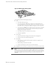
To install or remove a PIM, see “Replacing a PIM” on page 172.
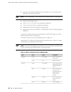
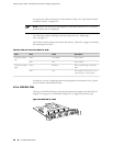
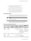
The G.SHDSL PIM has two LEDs to indicate the status of the PIM and its ports.
Table 33 on page 66 describes the meaning of the LED states.
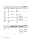
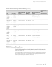
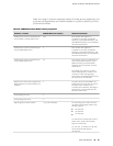
Table 33: LEDs for G.SHDSL PIMs
DescriptionStateColorLabel
Online with no alarms or failures.On steadilyGreen
ONLINE
Initialization of the PIM has failed.DisconnectedRed
PIM is booting.OffUnlit
Online with no alarms or failures.On steadilyGreen
STATUS
Active with a local alarm. The router has detected a
failure.
On steadilyRed
For alarms, see the configuring and monitoring alarms information in the J-series
Services Router Administration Guide.
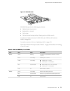
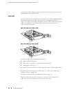
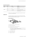
Avaya VoIP Modules
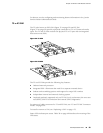
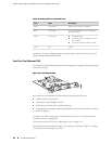
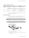
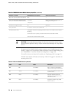
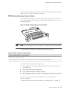
The Avaya VoIP modules are installed in a J-series chassis like Physical Interface
Modules (PIMs), but they are controlled by the Avaya Communication Manager
software rather than the JUNOS software.
CAUTION: PIMs and VoIP modules are not hot-swappable. You must power off the
Services Router before removing or inserting a PIM or VoIP module. Ensure that the
PIMs and VoIP modules are installed in the router chassis before booting up the
system.
CAUTION: The grounding cable for J-series routers must be, at minimum, 14 AWG
cable. For more information, see “Chassis Grounding” on page 123.
66 ■ Avaya VoIP Modules
J2320, J2350, J4350, and J6350 Services Router Getting Started Guide