


Solving power problems
Power problems can be difficult to solve. For example, a short circuit can exist
anywhere on any of the power distribution buses. Usually, a short circuit will cause
the power subsystem to shut down because of an overcurrent condition. To
diagnose a power problem, use the following general procedure:
1. Turn off the server and disconnect all power cords.
2. Check for loose cables in the power subsystem. Also check for short circuits, for
example, if a loose screw is causing a short circuit on a circuit board.
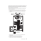
3. If a power-channel error LED on the system board is lit, perform the following
steps; otherwise, go to step Solving power problems. See“System-board LEDs”
on page 154 for the location of the power-channel error LEDs. Table 4 identifies
the components associated with each power channel, and the order in which to
troubleshoot the components.
a. Disconnect the cables and power cords to all internal and external devices.
Leave the power-supply cords connected.
b. Remove each component that is associated with the LED, one at a time, in
the sequence indicated in Table 4, restarting the server each time, until the
cause of the overcurrent condition is identified.
Important: Only a trained service technician should remove or replace a
FRU, such as a microprocessor or the system board. See Chapter 7, “Parts
listing, ThinkServer RD220 Type 3729, 3779, 3797, and 3798,” on page 231
to determine whether a component is a FRU.
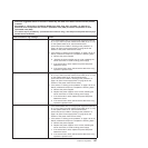
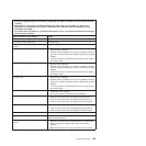
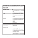
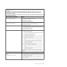
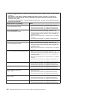
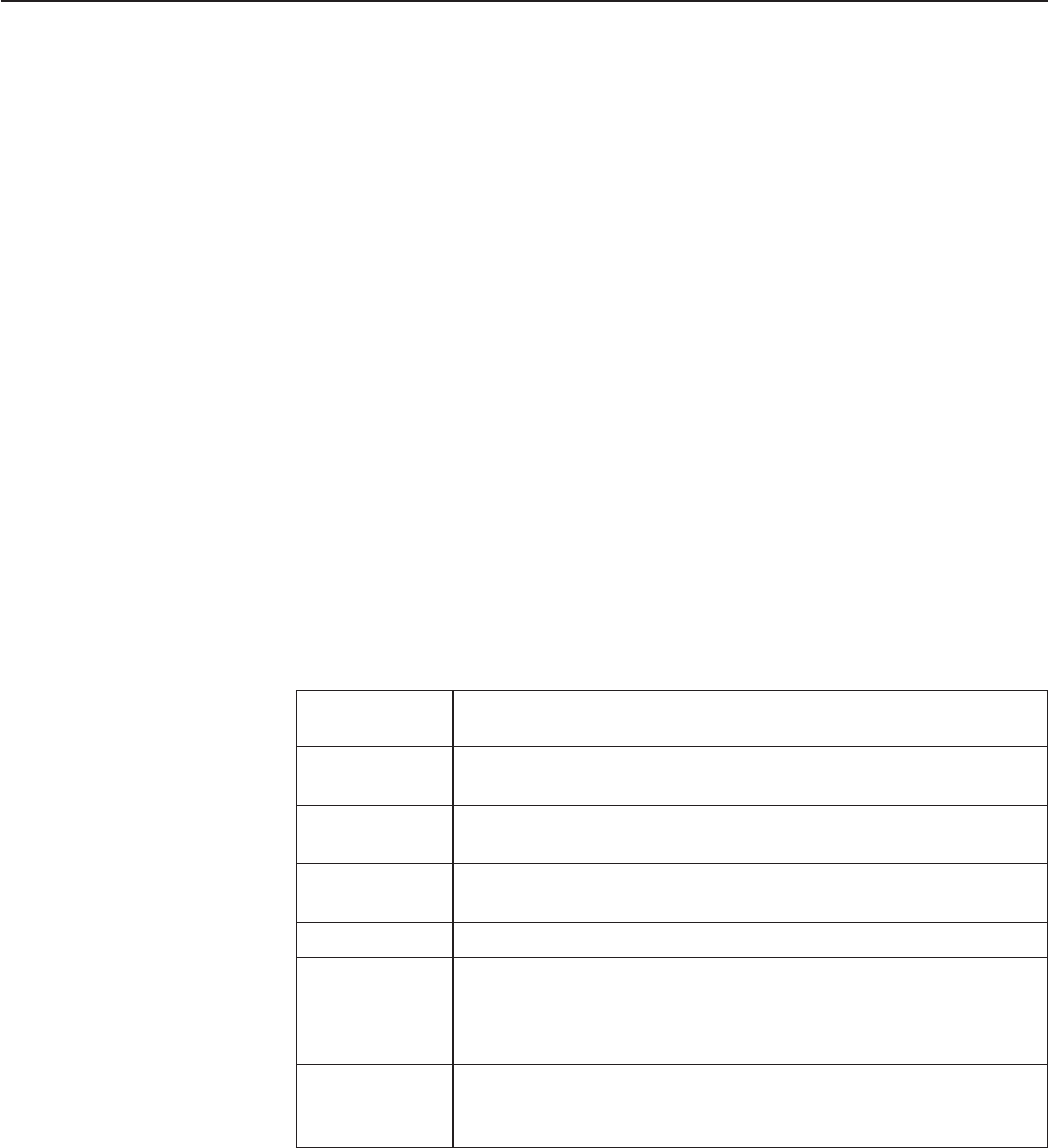
Table 4. Components associated with power-channel error LEDs
Power-channel
error LED Components
A CD/DVD drive (optical drive), fans, hard disk drives, hard disk
drive backplanes
B PCI riser-card assembly in PCI connector 1 on the system board,
DIMMs 1 through 16, microprocessor 2
C Tape drive if one is installed, SAS riser card assembly, DIMMs 1
through 8, microprocessor 1
D Microprocessor 1, system board
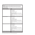
E Optional PCI video graphics adapter power cable if one is
installed (connector J154 on the system board), optional PCI
video graphics adapter if one is installed, PCI riser card assembly
in PCI connector 2 on the system board, microprocessor 2
240 V AUX All PCI adapters and PCI riser-card assemblies, SAS riser card
assembly, operator information panel assembly, optional two-port
Ethernet card if installed
c. Replace the identified component.
4. Remove the adapters and disconnect the cables and power cords to all internal
and external devices until the server is at the minimum configuration that is
required for the server to start (see “Features and technologies” on page 15 for
the minimum configuration).
5. Reconnect all power cords and turn on the server. If the server starts
successfully, replace the adapters and devices one at a time until the problem is
isolated.
If the server does not start from the minimum configuration, replace the components
in the minimum configuration one at a time until the problem is isolated.
Chapter 5. Diagnostics 143