


Checkpoint codes
A checkpoint code is a value produced by the UEFI indicating the point at which the
system stopped during startup and Power-On Self Test (POST); it does not provide
error codes or suggest replacement components. These codes may be used for
more in-depth troubleshooting by Lenovo support.
Checkpoint codes are shown on the checkpoint code display on the light path
diagnostics panel (see “Light path diagnostics LEDs” on page 44 for the location of
the display area). By using the checkpoint display, you do not have to wait for the
video to initialize each time you restart the server.
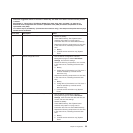
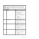
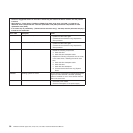
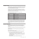
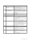
The following table describes the microprocessor checkpoint codes.
Table 2. Microprocessor Checkpoint Codes
Diagnostic Code Description
0010001 Microprocessor disabled
0010002 Microprocessor not supported
0010004 Microprocessor invalid
0011000 Invalid microprocessor type
0011002 Microprocessor mismatch
0011004 Microprocessor failed BIST
001100A Microcode update failed
There are two types of checkpoint codes: field programmable gate array (FPGA)
hardware checkpoint codes and UEFI checkpoint codes. The UEFI checkpoint
codes might change because of code sequence and timing changes or when the
UEFI code is updated. See http://www.lenovo.com/supportfor checkpoint code
information.
Light path diagnostics
Light path diagnostics is a system of LEDs on various external and internal
components of the server. When an error occurs, LEDs are lit throughout the
server. By viewing the LEDs in a particular order, you can often identify the source
of the error.
When LEDs are lit to indicate an error, they remain lit when the server is turned off,
provided that the server is still connected to power and the power supply is
operating correctly.
Before working inside the server to view light path diagnostics LEDs, read the
safety information that begins on page 3.
If an error occurs, view the light path diagnostics LEDs in the following order:
1. Look at the operator information panel on the front of the server.
v If the information LED is lit, it indicates that information about a suboptimal
condition in the server is available in the RMM system event log or in the
system event/error log.
v If the system-error LED is lit, it indicates that an error has occurred; go to
step 2 on page 42.
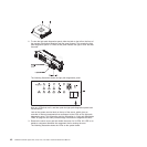
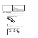
The following illustration shows the operator information panel.
Chapter 5. Diagnostics 41