


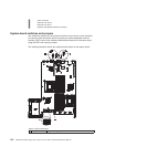

Table 5. Callout descriptions (continued)
1 UEFI boot recovery
jumper (J29)
v Pins 1 and 2: Normal (default) Loads the primary server
firmware (formerly called BIOS) ROM page.
v Pins 2 and 3: Loads the secondary (backup) server firmware
ROM page.
2 IMM recovery
jumper (J147)
v Pins 1 and 2: Normal (default) Loads the primary IMM firmware
ROM page.
v Pins 2 and 3: Loads the secondary (backup) IMM firmware
ROM page.
3 SW4 switch block
(reserved)
4 SW3 switch block
Notes:
1. If no jumper is present, the server responds as if the pins are set to 1 and 2.
2. Changing the position of the UEFI boot recovery jumper from pins 1 and 2 to pins 2 and
3 before the server is turned on alters which flash ROM page is loaded. Do not change
the jumper pin position after the server is turned on. This can cause an unpredictable
problem.
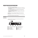
Table 6 describes the function of each switch on the switch block.
Table 6. Switch block 3, switches1-8
Switch
number Default value
Switch
description
8 Off Reserved.
7 Off Reserved.
6 Off Reserved.
5 Off Power-on password override. Changing the position of this switch bypasses the
power-on password check the next time the server is turned on and starts the Setup
utility so that you can change or delete the power-on password. You do not have to
move the switch back to the default position after the password is overridden.
Changing the position of this switch does not affect the administrator password check
if an administrator password is set.
4 Off Reserved.
3 Off Reserved.
2 Off Reserved.
1 Off Reserved.Clear
Clear CMOS. When this switch is toggled to On, it clears the CMOS data, which
clears the power-on password.
Important:
1. Before you change any switch settings or move any jumpers, turn off the server;
then, disconnect all power cords and external cables. (Review the information in
Chapter 2, “Safety information,” on page 3, “Installing optional devices and
replacing FRUs” on page 156, and “Turning off the server” on page 53.)
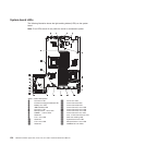
2. Any system-board switch or jumper blocks that are not shown in the illustrations
in this document are reserved.
Chapter 6. Removing and installing FRUs 153