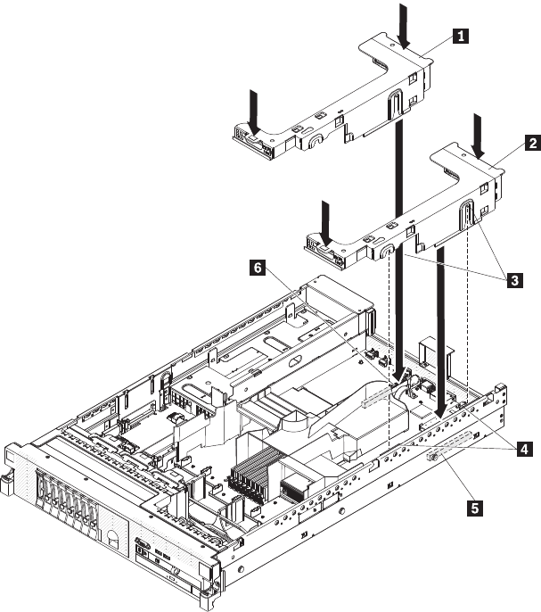
1 PCI riser-card assembly 2
2 PCI riser-card assembly 1
3 Alignment slots
4 Alignment brackets
5 PCI riser connector 1
6 PCI riser connector 2
v PCI riser connector 1: Carefully fit the two alignment slots on the side of the
assembly onto the two alignment brackets in the side of the chassis; align
the rear of the assembly with the guides on the rear of the server
v PCI riser connector 2: Carefully align the bottom edge (the contact edge) of
the riser-card assembly with the PCI riser-card connector on the system
board; align the rear of the assembly with the guides on the rear of the
server.
10. Press down on the assembly. Make sure that the riser-card assembly is fully
seated in the PCI riser-card connector on the system board.
11. Perform any configuration tasks that are required for the adapter.
If you have other optional devices to install or remove, do so now. Otherwise, go to
“Completing the installation” on page 227.
Installing the full-length-adapter bracket
If you are installing a full-length adapter in the upper riser-card PCI slot, you must
first install the full-length-adapter bracket in the end of the riser-card assembly.
Chapter 6. Removing and installing FRUs 183


