


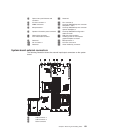
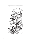
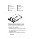
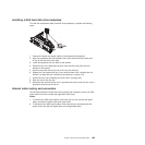
1 Cover 11 CD/DVD drive
2 PCI riser-card assembly 12 Operator information panel
3 PCI riser-card assembly 13 Front bezel (some models)
4 Heat sink 14 4-drive filler panel
5 Microprocessor 15 SAS hard disk drive backplanes
6 Heat-sink retention module 16 SAS riser card
7 DIMM 17 Fan bracket
8 System board 18 Fans
9 Power-supply filler panel 19 DIMM air baffle
10 Power supply 20 Microprocessor 2 air baffle
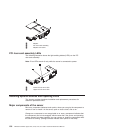
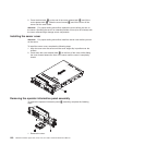
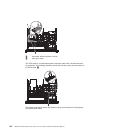
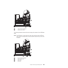
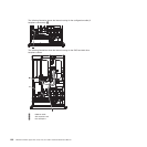
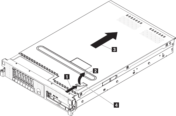
Removing the cover
The following illustration shows how to remove the cover.
Important: Before you install optional hardware, make sure that the server is
working correctly. Start the server, and make sure that the operating system starts,
if an operating system is installed, or that a 19990305 error code is displayed,
indicating that an operating system was not found but the server is otherwise
working correctly. If the server is not working correctly, see the “Diagnosing a
problem” on page 21 for diagnostic information.
To remove the cover, complete the following steps:
1. Read the safety information in the Installation and User Guide document.
2. If you are planning to view the error LEDs that are on the system board and
components, leave the server connected to power and go directly to step 4.
3. If you are planning to install or remove a microprocessor, memory module, PCI
adapter, battery, or other non-hot-swap optional device, turn off the server and
all attached devices and disconnect all external cables and power cords (see
“Turning off the server” on page 53).
4. Press down on the left and right side latches and pull the server out of the rack
enclosure until both slide rails lock.
Note: You can reach the cables on the rear of the server when the server is in
the locked position.
Chapter 6. Removing and installing FRUs 159