


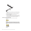

DIMM installation sequence
The server requires at least one DIMM per microprocessor. The server comes with
a minimum of two 1 GB DIMMs, installed in connectors 3 and 6. (Connectors 3 and
6 are the farthest connectors for channels 0 and 1 of microprocessor 1.) When you
install additional DIMMs, install them in the order shown in Table 9, to maintain
performance.
Important: If you have configured the server to use memory mirroring, do not use
the order in Table 9; go to “Memory mirroring” and use the installation order shown
there.
Table 9. DIMM installation sequence for non-mirroring (normal) mode
Installed microprocessors DIMM connector population sequence
Microprocessor socket 1 Install the DIMMs in the following sequence: 3, 6, 8, 2, 5, 7,
1, 4
Microprocessor socket 2 Install the DIMMs in the following sequence: 11, 14, 16, 10,
13, 15, 9, 12
Memory mirroring
Memory-mirroring mode replicates and stores data on two pairs of DIMMs within
two channels simultaneously. If a failure occurs, the memory controller switches
from the primary pair of memory DIMMs to the backup pair of DIMMs. You must
enable memory mirroring through the Setup utility. For details about enabling
memory mirroring, see “Memory mirroring.” When you use the memory mirroring
feature, consider the following information:
v When you use memory mirroring, you must install a pair of DIMMs at a time.
One DIMM must be in channel 0, and the mirroring DIMM must be in the same
connector in channel 1. The two DIMMs in each pair must be identical in size,
type, rank (single, dual, or quad), and organization. They do not have to be
identical in speed. The channels run at the speed of the slowest DIMM in any of
the channels. See Table 11 on page 192 for the DIMM connectors that are in
each pair.
v Channel 2, DIMM connectors 8 ,7, 15, and 16 are not used in memory-mirroring
mode.
v The maximum available memory is reduced to half of the installed memory when
memory mirroring is enabled. For example, if you install 64 GB of memory, only
32 GB of addressable memory is available when you use memory mirroring.
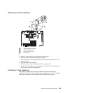
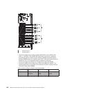
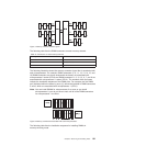
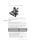
The following illustration shows the memory channel interface layout with the DIMM
installation sequence for mirroring mode. The numbers within the boxes indicate the
DIMM population sequence in pairs within the channels, and the numbers next to
the boxes indicate the DIMM connectors within the channels. For example, the
following illustration shows that the first pair of DIMMs (indicated by ones (1) inside
the boxes) should be installed in DIMM connector 3 on channel 0 and DIMM
connector 6 on channel 1. DIMM connectors 7, 8, 15, and 16 on channel 2 are not
used in memory-mirroring mode.
190 ThinkServer RD220 Types 3729, 3779, 3797, and 3798: Hardware Maintenance Manual