


v Microprocessor 1: PCI riser-card assembly 1 and DIMM air baffle (see
“Removing a PCI riser-card assembly” on page 167 and “Removing the
DIMM air baffle” on page 177)
v Microprocessor 2: PCI riser-card assembly 2 and microprocessor 2 air baffle
(see “Removing a PCI riser-card assembly” on page 167 and “Removing the
microprocessor 2 air baffle” on page 175).
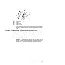
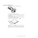
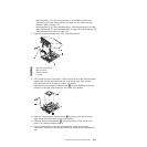
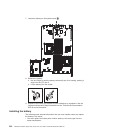
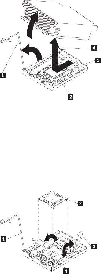
5. Open the heat-sink release lever to the fully open position.
1 Heat-sink release lever
2 Microprocessor
3 Retainer bracket
4 Lock tab
6. Lift the heat sink out of the server. If the heat sink sticks to the microprocessor,
slightly twist the heat sink back and forth to break the seal. After removal,
place the heat sink on its side on a clean, flat surface.
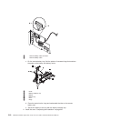
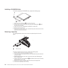
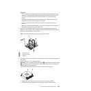
7. Release the microprocessor retention latch 1 by pressing down on the end,
moving it to the side, and releasing it to the open (up) position.
8. Open the microprocessor bracket frame 4 by lifting up the tab on the top
edge. Keep the bracket frame in the open position.
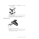
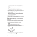
9. Carefully lift the microprocessor 2 straight up and out of the socket, and
place it on a static-protective surface.
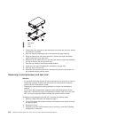
10. If you are instructed to return the microprocessor, follow all packaging
instructions, and use any packaging materials for shipping that are supplied to
you.
Chapter 6. Removing and installing FRUs 217