


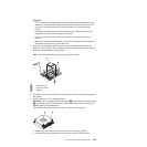
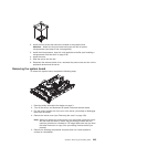
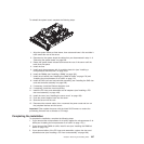

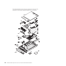

To reinstall the system board, complete the following steps.
1. Align the system board as tilted shown, then rotate and lower it flat and slide it
back toward the rear of the server.
2. Reconnect to the system board the cables that you disconnected in step 11 of
“Removing the system board” on page 225.
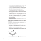
3. Rotate the system board release latch toward the rear of the server until the
latch clicks into place.
4. Install the fans.
5. Install each microprocessor with its matching heat sink (see “Installing a
microprocessor and heat sink” on page 218).
6. Install the DIMMs (see “Installing a DIMM” on page 192).
7. Install the air baffles (see “Installing the DIMM air baffle” on page 178) and
“Installing the microprocessor 2 air baffle” on page 176.
8. Install the SAS riser-card and controller assembly (see “Installing the SAS riser
card and controller assembly” on page 202).
9. If necessary, install the Ethernet daughter card.
10. If necessary, install the virtual media key.
11. Install the PCI riser-card assemblies and all adapters (see “Installing a PCI
riser-card assembly” on page 168).
12. Install the cover (see “Installing the server cover” on page 160).
13. Push the power supplies back into the server.
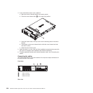
14. Slide the server into the rack.
15. Reconnect the external cables; then, reconnect the power cords and turn on
the peripheral devices and the server.
Important: Either update the server with the latest SAS firmware or restore the
pre-existing firmware from a diskette or CD image.
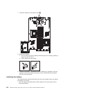
Completing the installation
To complete the installation, complete the following steps:
1. If you removed the microprocessor 2 air baffle, replace the microprocessor 2 air
baffle (see “Installing the microprocessor 2 air baffle” on page 176) ).
2. If you removed the DIMM air baffle, install it now (see “Installing the DIMM air
baffle” on page 178).
3. If you removed either of the PCI riser-card assemblies, replace the riser-card
assemblies now (see “Installing a PCI riser-card assembly” on page 168).
Chapter 6. Removing and installing FRUs 227