


Pinouts of back panel connectors 121
Pinouts of back panel connectors
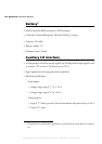
The back panel has the following connectors:
• Two serial port connectors.
• A video input connector ("Video in").
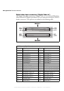
• Two digital video input connectors ("Digital Video in") (only if Matrox
Meteor-II /Digital for PC/104-Plus is purchased).
• Two Camera Link connectors ("Channel 1" and "Channel 2") (only if Matrox
Meteor-II /Camera Link for PC/104-Plus is purchased).
• An audio input (top) and an audio output (bottom) connector ("Audio").
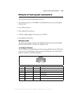
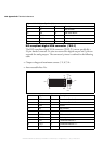
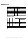
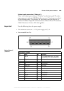
Serial port connectors
The two serial port connectors are 9-pin, D-SUB male connectors. Although they
are both configured for RS-232 standard, the configuration of the bottom
connector can be changed to accommodate the RS-422/RS-485 standard. For a
detailed description of how to do this, see the BIOS reference appendix.
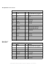
When the bottom serial port connector is configured for the RS-422/RS-485
standard, you can activate resistor termination on the serial port connector
through the internal dip switch. Refer to the subsection Internal dip switch in the
Pinouts of internal connectors and dip switches section of this appendix.
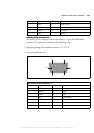
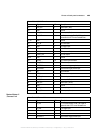
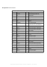
The pinouts for the serial ports are outlined in the following tables:
1
5
6
9
MATROX IMAGING est distribué par TECHWAY - www.techway.fr - info@techway.fr - +33 (0)1 64 86 58 30