


Connecting video input devices 31
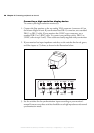
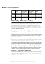
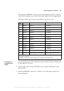
This cable has a DBHD44 connector on one side, and thirteen BNC connectors
on the other. It supports up to twelve video input signals and one trigger signal.
The thirteen BNC wires connect to the different cameras, as such:
Connecting to
composite input
signals
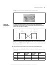
You can interface up to twelve composite cameras to Matrox Meteor-II /Standard
on the 4Sight-M. To do so:
1. Connect each camera to one of the BNC wires, using the information in the
previous table.
2. Attach the DBHD44 connector to "Video in", the video input connector of
Matrox 4Sight-M.
BNC#
1
Signal Composite camera input connector Y/C camera input connector
1 VID_IN1 Camera 1 Y (camera 1)
2 VID_IN2 Camera 2 C (camera 1)
3 VID_IN3 Camera 3 Y (camera 2)
4 VID_IN4 Camera 4 C (camera 2)
5 VID_IN5 Camera 5 C (camera 4)
6 VID_IN6 Camera 6 Y (camera 3)
7 VID_IN7 Camera 7 C (camera 3)
8 VID_IN8 Camera 8 Y (camera 4)
9 VID_IN9 Camera 9 Y (camera 5)
10 VID_IN10 Camera 10 C (camera 5)
11 VID_IN11 Camera 11 Y (camera 6)
12 VID_IN12 Camera 12 C (camera 6)
13 OPTOTRIG
External trigger input (OPTOTRIG+)
2
External trigger input (OPTOTRIG+)
2
1. The wire color associated with each BNC number can be found on the color code pinout chart included with the
DBHD44-TO-13BNC cable.
2. OPTOTRIG- is connected to the ground of the trigger source, and passes through the cable shield.
MATROX IMAGING est distribué par TECHWAY - www.techway.fr - info@techway.fr - +33 (0)1 64 86 58 30