


34 Chapter 2: Connecting peripherals to the unit
Connecting devices to the serial port
You can connect devices to the two serial ports using a 9-pin RS-232 or
RS-422/RS-485 serial port cable.
If you connect RS-422/RS-485 serial devices, remember to configure the serial
port to meet this standard. This is done by adjusting the internal dip switch.
Note that the RS-422/RS-485 standard cables are different from those meeting
the RS-232 standard. This is because RS-422/RS-485 specifies differential
signaling, and therefore its electrical requirements are different. In addition, the
function of the serial port connector’s pins are different when operating under
RS-422/RS-485. For details on the connector pinout of each interface, refer to
the Technical reference appendix.
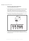
Connecting devices to the auxiliary I/O
interface
If you have purchased the integrated-unit version of Matrox 4Sight-M, you can
connect devices to the auxiliary I/O interface connector, located on the front panel
of the unit.
The auxiliary I/O interface supports up to 24 V. Each input can be driven by TTL
devices or other devices, up to a maximum of 24 V. Each output is capable of
sinking up to 100 mA (fuse protected) with a voltage up to 24 V. Auxiliary output
signals are only capable of sinking currents (using only the sink driver), that is,
auxiliary outputs are not capable of sourcing voltage. Essentially, instead of
transmitting a high or low voltage state, a current from a connected device is either
terminated (grounded) or not.
Connecting TTL
devices
To connect TTL devices to the external auxiliary I/O interface connector, you will
need a custom cable with a DBHD44 connector.
Pinout information for the auxiliary I/O connector can be found in the Technical
reference appendix. You can also refer to this appendix for information on where
a custom-mating connector can be obtained.
MATROX IMAGING est distribué par TECHWAY - www.techway.fr - info@techway.fr - +33 (0)1 64 86 58 30