


138 Appendix B: Technical reference
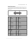
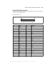
Power connectors for IDE devices and system power supply
The pinouts of the two 4-pin power connectors (one for connecting IDE devices
and one for connecting the power supply) are outlined in the section Motherboard,
earlier in this appendix.
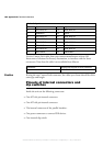
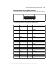
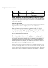
Internal dip switch
The internal dip switch allows you to activate resistor termination on your Matrox
4Sight-M unit, as well as to configure power-on and fan functions.
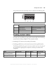
When the bottom serial port connector is configured for RS-422/RS-485
standard, you can adjust the termination. When activated, the terminal resistors
are connected between the RXD - (pin 2) and RXD + (pin 8) at 120 ohms. Refer
to the subsection Serial port connectors in the Pinouts of back panel connectors section
for more information on the serial port.
On the internal dip switch, you can also toggle the power-on features of the
Matrox 4Sight M unit to be set to automatic (ON) or manual (OFF). When you
set the power-on feature to automatic, the unit will power up automatically as
soon as it is plugged to a power source; when you set the power-on feature to
manual (the factory preset default), you will have to press the power button to
power up the unit once it is plugged to a power source.
You can also toggle the speed of the chassis fan to run at full-speed (ON) or in
automatic mode (OFF). When you set the fan to automatic mode, the fan will
run only when the CPU temperature is detected to be running too hot. This setting
reduces wear on the fan as opposed to running the fan constantly at full speed.
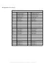
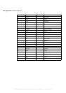
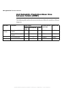
24 GND - Ground.
25 SEL I Select.
26 NC - Not connected.
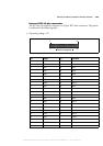
Pin Signal I/O Description
MATROX IMAGING est distribué par TECHWAY - www.techway.fr - info@techway.fr - +33 (0)1 64 86 58 30