


122 Appendix B: Technical reference
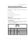
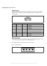
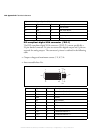
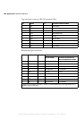
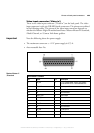
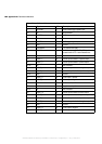
Top serial port connector (RS-232 standard only):
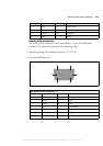
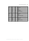
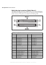
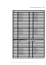
Bottom serial port connector:
Pin Signal I/O Description of RS-232 standard
1CD I Carrier detect.
2 RXD I Receive data.
3 TXD O Transmit data.
4 DTR O Data terminal ready.
5GND - Ground.
6 DSR I Data set ready.
7 RTS O Request to send.
8CTS I Clear to send.
9RI I Ring indicator.
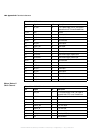
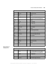
Pin Signal I/O Description
RS-232 standard RS-422/RS-485 standard with
resistor termination not activated
1 NC I Not connected. Not connected.
2 RXD I Receive data. RXD -.*
3 TXD O Transmit data. TX -.
4 NC O Not connected. Not connected.
5GND - Ground. Ground.
6 NC I Not connected. Not connected.
7 RTS O Request to send. TX +.
8 CTS I Clear to send. RXD +.*
9 NC I Not connected. Not connected.
* When resistor termination is activated, a resistor is connected between the receiver signals RXD- (pin 2)
and RXD+ (pin 8) at 120 ohms.
MATROX IMAGING est distribué par TECHWAY - www.techway.fr - info@techway.fr - +33 (0)1 64 86 58 30