


40 Chapter 3: Adding devices to the Matrox 4Sight-M motherboard
Introduction
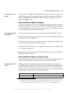
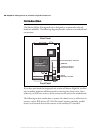
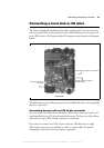
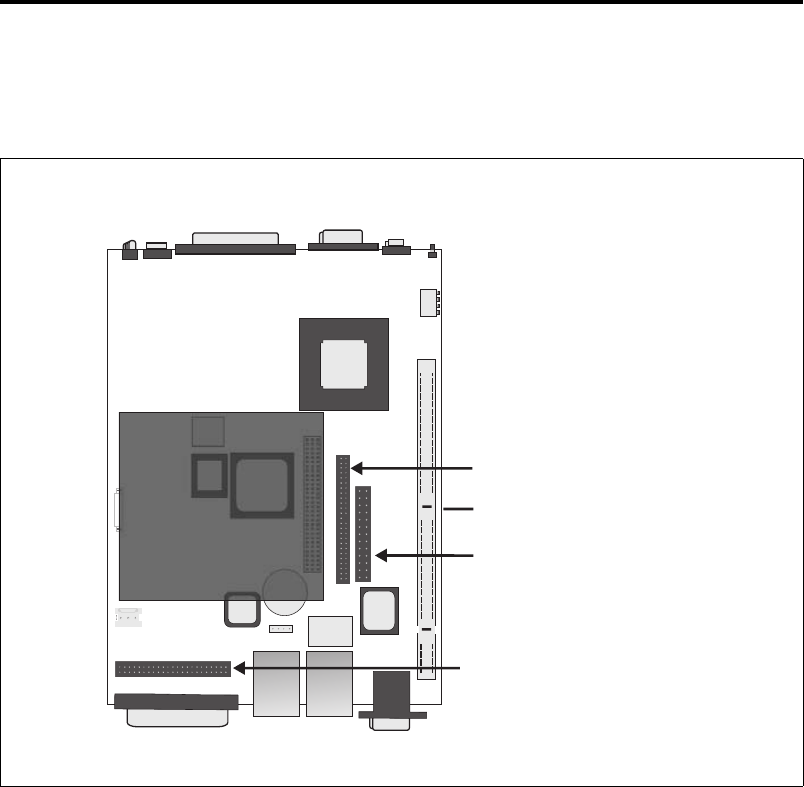
The Matrox 4Sight-M integrated unit is designed to accommodate selected
hardware additions. The following diagram provides a reference to motherboard
connections:
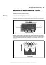
If you have purchased the integrated-unit version of Matrox 4Sight-M, the first
step in making hardware additions involves removing the chassis cover. Once
removed, you will have access to all the connectors located on the motherboard.
The following sections outline how to remove the chassis cover, as well as how to
connect various IDE devices, PC/104-Plus boards, memory modules, parallel
devices, and external devices that connect to the auxiliary I/O interface.
DIMM slot
Internal
ATA 44-pin connector
Back Panel
Front Panel
Internal connector of
the parallel interface
Internal ATA 40-pin connector
PC/104-
expansion site
Plus
TM
MATROX IMAGING est distribué par TECHWAY - www.techway.fr - info@techway.fr - +33 (0)1 64 86 58 30