


126 Appendix B: Technical reference
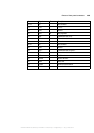
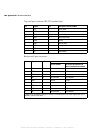
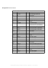
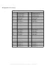
9 OPTOTRIG- I Opto-isolated trigger negative input.
10 NC Not connected.
11 LVDSTRIG+ I LVDS trigger positive input.
12 NC Not connected.
13 LVDSTRIG- I LVDS trigger negative input.
14 GND Ground.
15 EXTUSERIN1 I TTL external user input 1.
16 DC_OUT +12 V power supply. The DC_OUT signal is
protected with a 0.75 A auto-resettable fuse.
17-18 GND Ground.
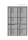
19 VSOUT_1- O Vertical synchronization 1 negative output.
20 VSOUT_1+ O Vertical synchronization 1 positive output.
21-22 NC Not connected.
23 HSOUT_1- O Horizontal synchronization 1 negative output.
24 HSOUT_1+ O Horizontal synchronization 1 positive output.
25-31 GND Ground.
32 CKOUT_1+ O Clock output 1 positive.
33 CKOUT_1- O Clock output 1 negative.
34 USIN0+ I Positive user input 0.
35 USIN0- I Negative user input 0.
36-37 NC Not connected.
38 VSOUT_0+ O Vertical synchronization 0 positive output.
39 VSOUT_0- O Vertical synchronization 0 negative output.
40 HSOUT_0+ O Horizontal synchronization 0 positive output.
41 HSOUT_0- O Horizontal synchronization 0 negative output.
42 GND Ground.
43 CKOUT_0- O Clock output 0 negative.
44 CKOUT_0+ O Clock output 0 positive.
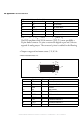
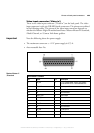
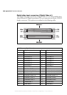
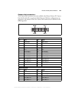
Matrox Meteor-II /Camera Link
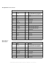
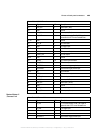
Pin Signal I/O Description
MATROX IMAGING est distribué par TECHWAY - www.techway.fr - info@techway.fr - +33 (0)1 64 86 58 30