


Connecting a hard disk or CD drive 45
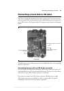
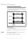
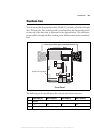
To connect the devices:
1. Using the three-connector flat-ribbon cable, attach one connector to the
motherboard, and attach the other two connectors to each device.
2. Set the jumpers on each device, so that one will operate in master mode, and the
other in slave mode.
3. Attach the custom power cable between the power-input connectors on your IDE
devices, and the power-supply connector on the motherboard.
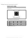
Important The voltages that can be drawn from the 4-pin power connector on the
motherboard are outlined in the Motherboard section of the Technical reference
appendix. If the IDE device you are connecting requires more power than that
specified in the table, use an external power supply. If you do not, you will risk
damaging the motherboard.
Connecting both types of IDE devices
You can connect both types of IDE devices to the motherboard simultaneously.
Follow the procedures outlined in the previous sections.
Drive assignments
By default, if a device is attached to the primary ATA 44-pin connector, it is
automatically identified as the primary master or primary slave by the BIOS.
Similarly, when a device is attached to the secondary ATA 40-pin connector, it
will be identified as the secondary master or secondary slave by the BIOS. Run
the BIOS Setup program to verify your devices’ configurations.
Master or slave designations are based on your device’s jumper settings, and are
used simply to differentiate between two devices connected to the same
ATA 40-pin or ATA 44-pin connector. There is no difference in performance
between these modes. For more information, refer to your device’s documentation.
MATROX IMAGING est distribué par TECHWAY - www.techway.fr - info@techway.fr - +33 (0)1 64 86 58 30