


Chapter 5. CONNECTOR
PINOUTS
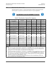
5.1 Connector Overview
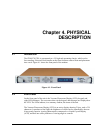
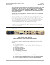
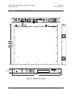
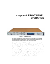
The rear panel connectors (Figure 5-1) provide all necessary external connections
between the modem and other equipment.
Figure 5-1. Rear Panel (shown with optional IP Module Ethernet Interface installed)
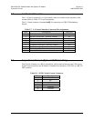
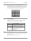
Table 5-1. External Connections
Name Connector Type Function
Rx IF 570L: ‘N’ type (female) 570: BNC (female) RF Input
Tx IF 570L: ‘N’ type (female) 570: BNC (female) RF Output
1:1 Control 9-pin D (female) Connects to CRS-170/180 switch
Data Interface 25-pin D (female) Data Input/Output
External Reference BNC (female) Input
Remote Control 9-pin D (male) Serial Remote Interface
Console RJ-11 Serial Console Interface
10/100 Ethernet Traffic RJ-45 Ethernet Traffic and M&C
10/100 Ethernet M&C RJ-45 Upgrade of base modem M&C
Alarms 15-pin D (male) Form C Alarms
Balanced G.703 15-pin D (female) Balanced G.703 Data
Rx Unbalanced BNC (female) Receive G.703 Data
Tx Unbalanced BNC (female) Transmit G.703 Data
5–1