


CDM-570/570L Satellite Modem with Optional IP Module Revision 4
Connector Pinouts MN/CDM570L.IOM
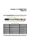
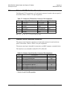
5.3 Balanced G.703 Interface Connector
The Balanced G.703 connection is a 15-pin female connector located on the rear panel of
the modem. Refer to
Table 5-3 for pin assignments.
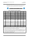
Table 5-3. Balanced G.703 Interface Connector Pin Assignments
Pin # Signal Function Name Direction
1 Tx G.703 - Tx G.703 In In
9 Tx G.703 + Tx G.703 In In
2 Ground GND
3 Rx G.703 - Rx G.703 Out Out
11 Rx G.703 + Rx G.703 Out Out
4 Ground GND
Pins 5, 6, 7, 8, 10, 12, 13, 14 and 15 are not used.
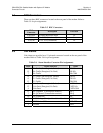
5.4 Remote Control Interface Connector
The remote control interface connection is a 9-pin male connector located on the rear
panel of the modem. Refer to
Table 5-4 for pin assignments.
The remote control port is intended for connection to an M&C computer, or terminal device.
This interface is user selectable for either EIA-232 or EIA-485.
Table 5-4. Remote Control Interface Connector Pin Assignments
Pin # Description Direction
1 Ground
2 EIA-232 Transmit Data Out
3 EIA-232 Receive Data In
4 Reserved - do not connect to this pin
5 Ground
6 EIA-485 Receive Data B * In
7 EIA-485 Receive Data A * In
8 EIA-485 Transmit Data B Out
9 EIA-485 Transmit Data A Out
* Use for 2-wire EIA-485 operation
5–3