


Multi-Tech Systems, Inc. 135
Appendix A – Cable Pin-outs
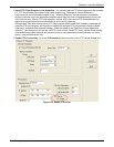
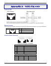
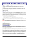
Command Cable
RJ-45 Connector End-to-End Pin Info
1 2 3 4 5 6 7 8
RJ-45 connector plugs into Command Port of MultiVOIP.
DB-9 connector plugs into serial port of command PC (which runs MultiVOIP configuration software).
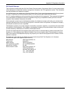
Ethernet Connector
The functions of the individual conductors of the MultiVOIP’s Ethernet port are shown on a pin-by-pin basis below.
RJ-45 Ethernet Connector Pin Circuit Signal Name
1 2 3 4 5 6 7 8
1 TD+ Data Transmit Positive
2 TD- Data Transmit Negative
3 RD+ Data Receive Positive
6 RD- Data Receive Negative
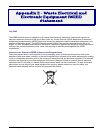
Voice/Fax Channel Connectors
Figure B-1: RJ-48 & RJ-11 Connectors
Pin Functions (E&M Interface)
Pin Desc
r
iption Function
1 M Input
2 E Output
3 T1 4-Wire Output
4 R 4-Wire Input, 2-Wire Input
5 T 4-Wire Input, 2-Wire Input
6 R1 4-Wire Output
7 SG Signal Ground (Output)
8 SB Signal Battery (Output)
Pin Functions (FXS/FXO Interface)
FXS Pin Description FXO Pin Description
2 N/C 2 N/C
3 Ring 3 Tip
4 Tip 4 Ring
5 N/C 5 N/C