


Multi-Tech Systems, Inc. 137
Appendix C – Installation Instructions
for MVP428 Upgrade Card
Installing the MVP428 Upgrade Card
In this procedure, you will install an additional circuit board into the MVP410, improving it from a 4-channel VOIP
to an 8-channel VOIP.
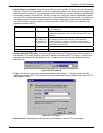
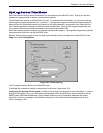
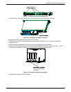
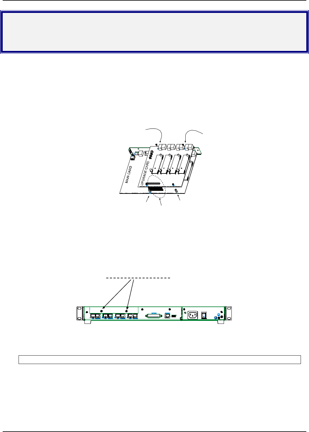
Summary: (A) Attach four standoffs to main circuit card.
(B) Mate the 60-pin connectors (male connector on main circuit card; female on upgrade card).
(C) Attach upgrade card to main circuit card (4 screws).
*
*
(A)
*
Add standoffs here
(2 places).
Replace main card screws
with standoffs here
(2 places).
(B)
Mate 60-pin
connectors.
(C)
Attach upgrade card
(screws into standoffs
-- 4 places).
Figure C-1: MVP 248 installation
Procedure in Detail
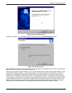
1. Power down and unplug the MVP410 unit.
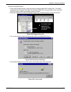
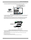
2. Using a Phillips driver, remove the blank cover plate at the rear of the MVP410 chassis. Save the screws.
screws on blank cover plate (2)
Figure C-2: Remove screws from cover plate
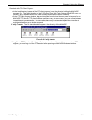
3. Using a Phillips driver, remove the three screws that secure the main circuit board and back panel
assembly to the chassis.
Important: Follow standard ESD precautions to protect the circuit board from static electricity damage.