


Installation and configuration 67
Nortel Integrated Conference Bridge Service Implementation Guide
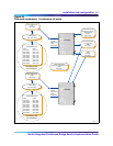
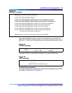
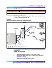
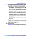
Refer to Figure 27 when connecting the Maintenance terminal (that is,
VT100) in the following procedures.
Figure 27
Terminal connection through the Ethernet Adapter
Procedure 5
Access the ICB directly
1 Position the Maintenance terminal on a desk near the system.
2 Verify that the Ethernet Adapter card is on the I/O panel as described in
Procedure 4 on page 66.
3 Plug the terminal cable DB-9 female connector into the DB-9 male connector
on the Ethernet Adapter card on the I/O panel.
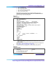
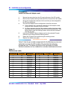
12 12 Reserved 25 N.C. Not Connected
13 23 LAN_Rx+
Table 12
Maintenance cable (Continued)
J2 DB-25 pin J1 50-pin Description J2 DB-25 pin J1 50-pin Description
G100013
Backplane
I/O Panel
Maintenance Terminal
Modem
Hub
ICB Card
DB-9
DB-25
RJ-45
RJ-45
Cable
A0601464
Cable
Backplane
Cable
Ethernet
Adapter
Indicate three ways of connecting the terminal.
1
1 2 3
2
3