


Provisioning Page 111 of 544
Option 11C and 11C Mini Technical Reference Guide
• battery backup time for the NTAK75
• battery backup time for the NTAK76
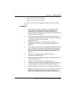
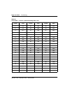
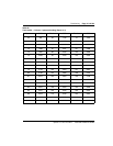
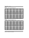
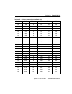
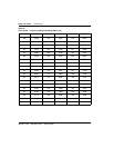
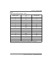
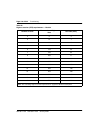
Use the circuit-card power-consumption table and worksheets provided
below.
Procedure
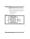
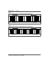
1 Determine the circuit card configuration in each system cabinet.
Record the card codes against their cabinet slot numbers, on
“Worksheet Ga: System power consumption: Main cabinet” on
page 146 through “Worksheet Ge: System power consumption: fourth
expansion cabinet” on page 150.
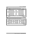
2 For each circuit card, transfer the power consumption values from
“Worksheet G: System power consumption” on page 144 to the power-
consumption column on the corresponding
Worksheets Ga - Ge.
3 Calculate the total option 11C system power consumption on
“Worksheet Gf: Total Option 11C system power consumption” on
page 151.
4 If your system is AC-powered, go to “Worksheet H: Battery current and
AC line calculation for AC systems using NTAK75 and NTAK76” on
page 153. If your system is DC-powered, go to“Worksheet I: Battery
current calculation for customer-provided DC reserve power” on
page 154.
5 Transfer the Pout (Main) and Pout (Expan.) values from
Worksheet G to Worksheet H or I.
6 Calculate Pin (Main), I Batt (Main), Pin (Expan), and I Batt (Expan) as
shown on Worksheet H or I.
7 Calculate Iline if required, as shown on Worksheet H.
8 Transfer the values calculated for I Batt (Main) and I Batt (Expan), onto
the NTAK75/QBL24A1 and the NTAK76 discharge time graphs.
9 Select the battery unit that provides the most appropriate backup time.
Note: For customer-provided DC reserve power systems, use I Batt
(Main) and I Batt (Expan) along with the battery manufacturer’s
specifications to determine battery requirements and backup times.