


M2250 Attendant Console Page 359 of 544
Option 11C and 11C Mini Technical Reference Guide
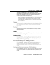
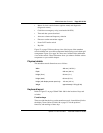
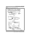
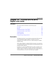
Figure 53
M2250 attendant console—top view
Switches
A slider switch, located in the bottom row of keys, between columns DI/EI
and FI (see Figure 53), controls the handset and headset receive volume level.
The Power Fail Transfer (PFT) switch is located in the baseplate. Both the
line connector and the RS-232 connector for the PC port are located at the
back of the attendant console.
Shift key
The shift key, mentioned earlier, is positioned in column FK, row 1, just
above the Hold key. It is used to access Level 1 mode functions.
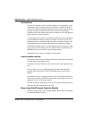
Handset and headset jacks
Two jack-pairs are provided for plugging in handsets or headsets. The jacks
are located on both sides of the console beneath the faceplate in the recessed
area shown by the arrows. The console accepts both carbon and electret
headsets and automatically adapts itself to each type.
Note: Electret headsets and handsets are polarity sensitive and must be
correctly inserted into the jack.
LCD indicators
The LCD indicators used on the M2250 are half-diamond shaped symbols
which normally point towards the key with which they are associated, except
in the QMT2 mode of operation and the loop keys where there are two LCDs
associated with each key.
Every LCD can flash at 30, 60, and 120 impulses per minute (ipm).
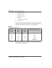
Display screen messages
The following messages may appear on the display screen:
• Source and destination information (line 2 and line 3 respectively)
• MN (minor alarm)
• MJ (major alarm)
• C/H(CAS/History File)