


NTAK20 clock controller Page 507 of 544
Option 11C and 11C Mini Technical Reference Guide
• CPU interface
• external timing interface
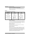
A description of each block follows.
Phase difference detector circuit
This circuit, under firmware control, allows a phase difference measurement
to be taken between the reference entering the PLL and the system clock.
The phase difference is used for making frequency measurements, and
evaluating input jitter and PLL performance.
Digital phase lock loops
The main digital PLL enables the clock controller. to provide a system clock
to the CPU. This clock is both phase and frequency locked to a known
incoming reference.
The hardware has a locking range of +
4.6 ppm for Stratum 3ND and
+
50 ppm for Stratum 4 (CCITT).
A second PLL on board the clock controller provides the means for
monitoring another reference. Note that the error signal of this PLL is routed
to the phase difference detector circuit so the microprocessor can process it.