


Page 382 of 544 NT8D14 Universal Trunk Card
553-3011-100 Standard 14.00 January 2002
When the card is installed, the red Light Emitting Diode (LED) on the
faceplate flashes as the self-test runs. If the self-test completes successfully,
the card is automatically enabled (if it is configured in software) and the LED
goes out. If the self-test fails, the LED lights steadily and remains lit. The
LED will also light and remain lit if one or more units on the card becomes
disabled after the card is operating.
Each unit on the card connects to the backplane through an 80-pin connector,
the backplane is cabled to the Input/Output (I/O) panel, and the I/O panel is
cabled to the cross-connect terminal.
At the cross-connect terminal, each unit connects to external apparatus, such
as Central Office facilities or recorded announcement equipment. Each unit
connects to external apparatus by tip and ring leads which carry voice,
ringing, tone signaling, and battery.
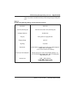
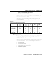
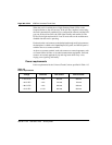
Power requirements
Power requirements for the Universal Trunk Card are specified in Table 115.
Table 115
Power requirements
Voltage Tolerance Idle current Active current
± 15.0 V DC ± 5% 306 ma 306 ma
+ 8.5 V DC ± 2% 120 ma 120 ma
- 48.0 V DC ± 5% 346 ma 346 ma
+ 5.0 V DC ± 10% 350 ma 350 ma