


Page 454 of 544 NTAK09 1.5 Mb DTI/PRI card
553-3011-100 Standard 14.00 January 2002
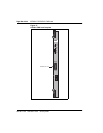
Connector pinout
The connection to the external digital carrier is via a 15 position Male D type
connector.
Clock controller interface
The purpose of the clock controller interface is to provide the recovered clock
from the external digital facility to the clock controller daughterboard via the
backplane. Depending on the equipped state of the clock controller, the clock
controller interface enables or disables the appropriate reference clock
source, in conjunction with software.
Clock rate converter
The 1.5 Mb clock is generated by a phase-locked loop (PLL). The PLL
synchronizes the 1.5 Mb DS1 clock to the 2.56 Mb system clock through the
common multiple of 8 kHz by using the main frame synchronization signal.
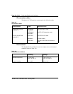
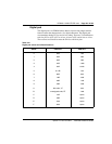
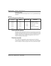
Table 142
DS-1 line interface pinout for NTBK04 cable
From 50-pin MDF
connector
to DB-15 signal name description
pin 48 pin 1 T transmit tip to network
pin 23 pin 9 R transmit ring to network
pin 25 pin 2 FGND frame ground
pin 49 pin 3 T1 receive tip from network
pin 24 pin 11 R1 receive ring from network