


Page 372 of 544 NT8D09 Analog Message Waiting Line Card
553-3011-100 Standard 14.00 January 2002
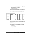
The analog message waiting line card interfaces to and is compatible with the
equipment listed in Table 109.
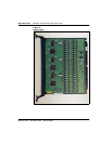
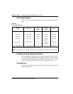
Physical
In Meridian 1 Option 11C systems the NT8D09 Analog Message Waiting
Line Card is installed in slots 1 through 10 of the Main cabinet, or in slots 11
through 50 in the Expansion cabinets. In Option 11C Mini, the card is
installed in slots 1 to 3 in the main chassis, or 7 to 10 in the chassis expander.
The line card circuits connects to the backplane through a 160-pin connector.
The backplane is cabled to a connector in the bottom of the cabinet which is
cabled to the cross-connect terminal (main distribution frame) through 25-
pair cables. Station apparatus then connects to the card at the cross-connect
terminal.
The faceplate of the analog message waiting line card is equipped with a red
light emitting diode (LED) which lights when the card is disabled. At power-
up, the LED flashes as the analog line card runs a self-test. If the test
completes successfully, the card is automatically enabled (if it is configured
in software) and the LED goes out.
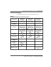
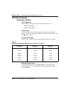
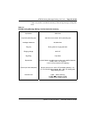
Table 109
NT8D09 Analog Message Waiting Line Card application and compatibility
Equipment Specifications
500 type rotary dial sets (or equivalent):
dial speed 8.0 to 12.5 pps
percent break 58 to 70%
interdigital time 150 ms
2500 type Digitone sets (or equivalent):
frequency accuracy + 1.5%
pulse duration 40 ms
interdigital time 40 ms
speed 12.5 digits/s