


Page 526 of 544 NT5D14 Line Side T-1 card
553-3011-100 Standard 14.00 January 2002
The line side T-1 card emulates an analog line card to the Option 11C system
software; therefore, each channel is independently configurable by software
control in the Single-line Telephone Administration program (LD 10). The
line side T-1 card also comes equipped with a Man-Machine Interface (MMI)
maintenance program. This feature provides diagnostic information
regarding the status of the T-1 link.
Physical description
The line side T-1 card mounts into any two consecutive IPE slots. The card
consists of a motherboard and a daughterboard; both are printed on standard
circuit board.
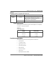
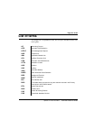
In general, the LEDs operate as shown in Table .
Table 162
NT5D14AA Line Side T-1 Faceplate LEDs (Part 1 of 2)
LED State Definition
STATUS On (Red) The NT5D14AA card either failed its self-test or it
hasn’t yet been configured in software.
Off The card is in an active state
RED On (Red) A red alarm has been detected from the T-1 link.
(This includes, but is not limited to: not receiving a
signal, the signal has exceeded bit error thresholds
or frame slip thresholds.)
Off No red alarm exists.
YEL On (Yellow) A yellow alarm state has been detected from the
terminal equipment side of the T-1 link. If the
terminal equipment detects a red alarm condition, it
may send a yellow alarm signal to the line side T-1
card (this depends on whether or not your terminal
equipment supports this feature).
Off No yellow alarm.