


NT1R20 Off Premise Station (OPS) analog line card Page 427 of 544
Option 11C and 11C Mini Technical Reference Guide
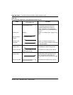
— self-test status
— programmed configuration status
• receipt and implementation of card configuration:
— of the codecs
— enabling/disabling of individual units or entire card
— programming of input/output interface control circuits for
administration of line interface unit operation
— maintenance diagnostics
— transmission loss levels
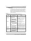
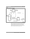
Signaling and control—This portion of the card provides circuits that
establish, supervise, and take down call connections. These circuits work
with the system CPU to operate line interface circuits during calls. The
circuits receive outgoing call signaling messages from the CPU and return
incoming call status information over the DS-30X network loop.
Circuit Power
The +8.5 V dc input is regulated down to + 5 V dc for use by the digital logic
circuits. All other power to the card is used by the line interface circuits.
Foreign and surge voltage protection
The OPS analog line card meets UL-1489 and CS03 over-voltage (power
cross) specifications and FCC Part 68 requirements for hazardous and surge
voltage limits.
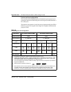
Software service changes
Individual line interface units on the OPS analog line card are configured to
either OPS (for OPS application) or ONS (for ONS application) class-of-
service (CLS) in the Single-line Telephone Administration program (LD10)
(see Table 133). LD10 is also used to select unit terminating impedance and
balance network impedance at the TIMP and BIMP prompts, respectively.
See the Maintenance (553-3001-511) for LD 10 service change instructions.