


NTAK09 1.5 Mb DTI/PRI card Page 449 of 544
Option 11C and 11C Mini Technical Reference Guide
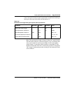
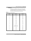
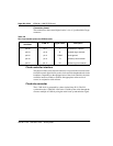
In general, the first five LEDs operate as follows:
• During system power up, the LEDs are on.
• When the self-test is in progress, the LEDs flash on and off three times,
then go into their appropriate states, as shown in Table 139.
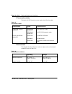
Power requirements
The DTI/PRI obtains its power from the backplane, and draws less than 2
amps on +5 V, 50 mA on +12 V and 50 mA on -12 V.
Foreign and surge voltage protection
Lightning protectors must be installed between an external T-1 carrier facility
and the Option 11C cabinet. For public T-1 facilities, this protection is
provided by the local operating company. In a private T-1 facility
environment (a campus, for example), the NTAK92 protection assembly may
be used.
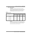
Table 139
NTAK09 LED states
LED State Definition
DIS On (Red) The NTAK09 circuit card is disabled.
Off The NTAK09 is not in a disabled state.
ACT On (Green) The NTAK09 circuit card is in an active state. No alarm states
exist, the card is not disabled, nor is it in a loopback state.
Off An alarm state or loopback state exists, or the card has been
disabled. See the other faceplate LEDs for more information.
RED On (Red) A red-alarm state has been detected.
Off No red alarm.
YEL On (Yellow) A yellow alarm state has been detected.
Off No yellow alarm.
LBK On (Green) NTAK09 is in loop-back mode.
Off NTAK09 is not in loop-back mode.