


NTAK10 2.0 Mb DTI card Page 469 of 544
Option 11C and 11C Mini Technical Reference Guide
In general, the LEDs operate as follows:
• after the card is plugged in, the LEDs (a-e) are turned on by the power-
up circuit. The clock controller LED is independently controlled by its
own microprocessor
• after initialization, the LEDs (a-e) flash three times (0.5 seconds on, 0.5
seconds off) and then individual LEDs will go into appropriate states, as
shown in Table •.
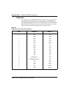
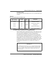
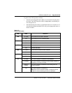
Table 147
NTAK10 LED states
LED State Definition
DIS On (Red) The NTAK10 circuit card is disabled.
Off The NTAK10 is not in a disabled state.
OOS On (Yellow) The NTAK10 is in an out of service state
Off The NTAK10 is not in an out of service state
NEA On (Yellow) A near end alarm state has been detected
Off No near end alarm
FEA On (Yellow) A far end alarm state has been detected
Off No far end alarm
LBK On (Yellow) NTAK10 is in loop-back mode
Off NTAK10 is not in loop-back mode
CC On (Red) The clock controller is switched on and disabled
On (Green) The clock controller is switched on and is either locked to a
reference or is in free-run mode
Flashing
(Green)
The clock controller is switched on and locking onto the
primary reference
Off The clock controller is switched off
Note: See “Clock controller interface” on page 474 in this
chapter for more on tracking and free-run operation.