


Page 428 of 544 NT1R20 Off Premise Station (OPS) analog line card
553-3011-100 Standard 14.00 January 2002
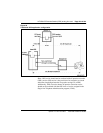
Port-to-port loss configuration
The loss plan for the OPS analog line card determines port-to-port loss for
connections between an OPS analog line card unit (port) and other Meridian 1
PE or IPE ports.
The transmission properties of each line unit are characterized by the OPS or
ONS class-of-service assigned in the Single-line Telephone Administration
program (LD10).
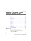
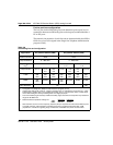
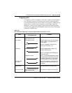
Table 133
OPS analog line card configuration
Application On-premise station (ONS) Off-premise station (OPS)
Class of service ONS OPS
Loop resistance 0 - 460 ohm 0 - 2300 ohm
Jumper strap set-
ting
b
Both JX. 0 and JX 1 off Both JX. 0 and JX.
1 off
Both JX. 0 and JX.
1 on
Loop loss dB
c
0-1.5 >1.5-
2.5
>2.5-
3.0
0-1.5 >1.5-
2.5
>2.5-
4.5
>4.5-15
TIMP 600
ohm
600
ohm
600
ohm
600
ohm
600
ohm
600
ohm
600
ohm
BIMP 600
ohm
3COM 3CM2 600
ohm
3COM 3CM2 3CM2
Gain treatment
e
No Yes
a. Configured in the Single line Telephone Administration program (LD 10).
b. Jumper strap settings JX 0 and JX. 1 apply to all eight units; “X” indicates the unit number, 0-7. “OFF”
indicates that a jumper strap is not installed across both pins on a jumper block. Store unused straps
on the OPS analog line card by installing them on a single jumper pin.
c. Loss of untreated (no gain devices) metallic line facility. Upper loss limits correspond to loop resistance
ranges for 26 AWG wire.
d. Default software impedance settings are: ONS CLS
OPS CLS
TIMP: 600 ohm 600 ohm
BIMP: 600 ohm 3COM2
e. Gain treatment, such as a voice frequency repeater (VFR) is required to limit the actual OPS loop loss
to 4.5 dB, maximum. VFR treatment of metallic loops having untreated loss greater than 15dB
(equivalent to a maximum signaling range of 2300 ohm on 26 AWG wire) is not recommended.