


General Installation Passport 4400 Hardware Installation Module
10-7
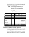
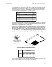
6. Refer to Section 9, Power Supplies, to verify that the correct number of
power supplies are configured for the number of modules used in the
unit.
7. Strap the module, (refer to the section for the individual module).
— Section 4, Data Modules
— Section 5, T1, E1, and Digital Voice Modules
— Section 6, Analog Voice Modules.
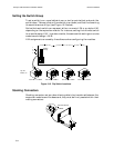
8. Set the module location switch group (see page 10-4).
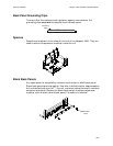
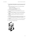
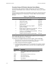
9. Place a spacer between the previous module and the module to be
installed.
10. Place the module on the spacer in front and on the previous module’s
back panel in the back. The back panel goes on the outside of the
chassis.
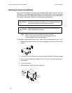
11. Connect the stacking connector. Press down so that they mate
completely.
12. Align the two holes on the module back with the two holes on the back
of the chassis. Using screws, join the back panel to the chassis.
13. Continue to stack modules using steps 7-12 until all modules have been
installed.
14. Ensure that any blank module locations contain blank back panels.
15. Close the unit by replacing the cover.