


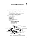
Ethernet Base Module Passport 4400 Hardware Installation Manual
3-5
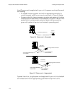
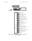
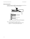
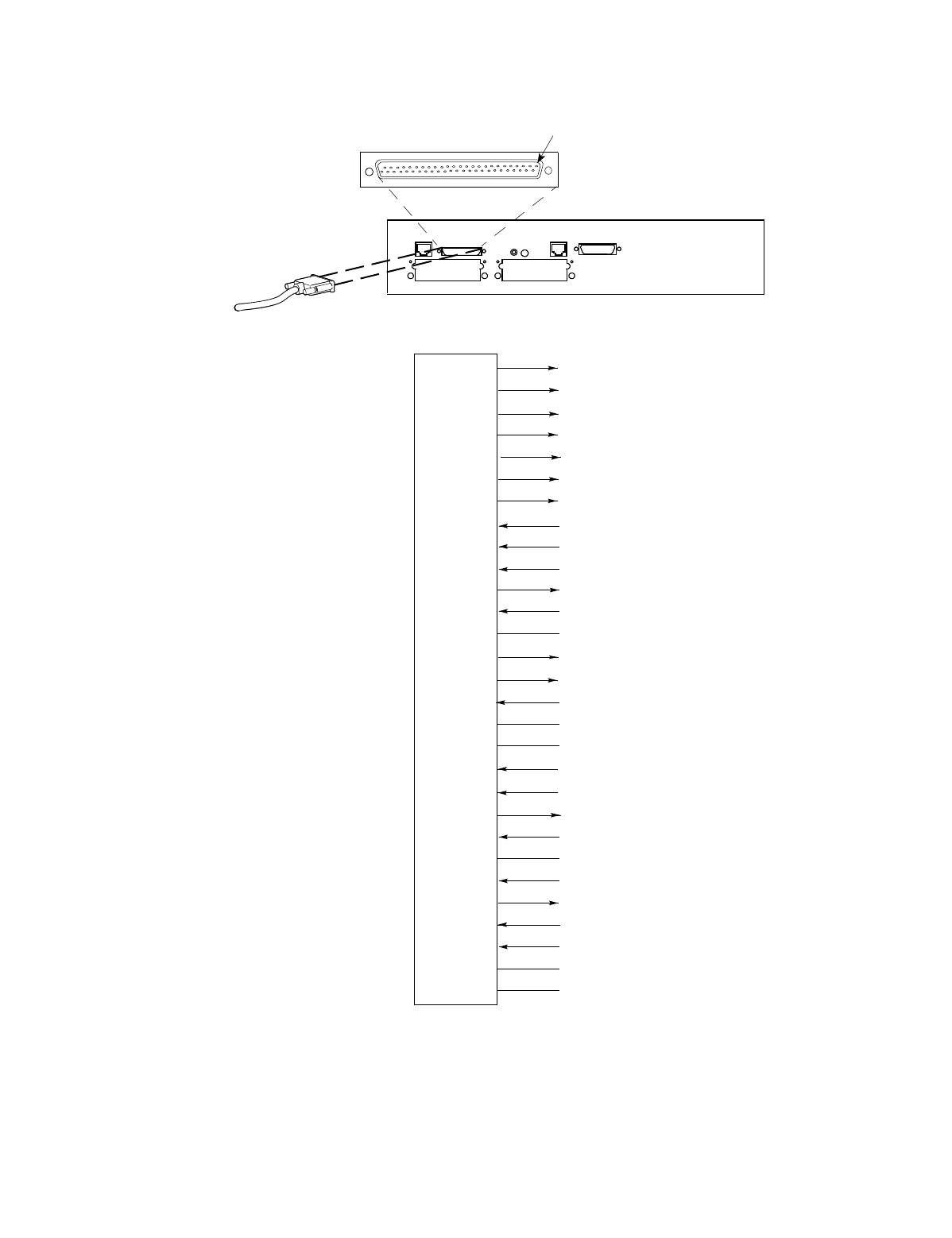
Figure 3-5. Pin Assignments Frame Relay DCE Serial Access Port (Port 1)
and All Data Modules
Pin 1
RS-232/V.24 Receive Data
RS-232/V.24 Receive Data Clock
RS-232/V.24 External Transmit Data Clock
V.35 Transmit Data
V.35 External Receive Data Clock
V.35 External Transmit Data Clock
V.36/X.21 Transmit Data
V.36/X.21 External Receive Clock
V.36 External Transmit Clock/X.21
V.35/V.36/X.21 Receive Data
V.35/V.36/X.21 Transmit Data Clock
V.35/V.36 Receive Data Clock/X.21 Indication
RS-232/V.24/V.35/V.36 Ready to Send
RS-232/V.24/V.35/V.36 Data Terminal Ready
Unassigned
RS-232/V.24/V.35/V.36 Clear to Send/ X.21
RS-232/V.24/V.35/V.36 Carrier Detect
V.35 Input Termination Ground
Interface Type Indication
Cable Present Status
DTE Signal Return
Logic Ground
Logic Ground
Logic Ground
41
42
40
3, 28
4, 29
5, 30
6, 31
7, 32
8, 33
20, 45
21, 46
22, 47
12
37
13
9, 34
11, 36
23, 24, 25
1, 2
14
18
26, 27, 39
43, 48, 49
50
50-Pin Connector
Reserved
19, 38, 44
RS-232/V.24 Transmit Data
RS-232/V.24 Transmit Data Clock
RS-232/V.24 External Receive Data Clock
16
17
15
RS-232/V.24/V.35/V.36 Data Set Ready
10, 35