


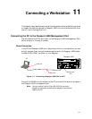


Connecting a WorkstationVariable Document_Name
11-4
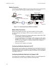
Procedure Using a US Robotics Sportster Series Modem
The following is an example of modem configuration using a US Robotics
Sportster Series Modem (other modems will be different, consult your modem
manual).
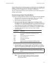
Configurating the modem requires hardware configuration (dip switches) and
software configuration (AT commands). The chart below lists the hardware
settings.
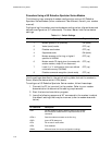
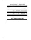
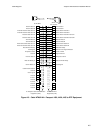
Table 11-1. Switch Settings
Use the settings described in the switch setting table, but set the modem to
Smart Mode (hardware switch 8 ON (down).
To configure a US Robotics Sportster Series modem, follow these steps:
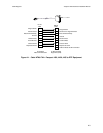
1. Connect the PC (or terminal) to the modem. Refer to your modem
documentation to determine the cabling requirements.
2. Start the terminal emulation program.
3. Issue the following sequence of AT commands to the modem to adjust
the default settings that may be incorrect (refer to modem documen-
tation).
Switch Number Setting Description Required Setting
1 Modem ignores DTR (override) ON (down)
2 Verbal (word) results OFF (up)
3 Disables result codes OFF (up)
4 Suppresses echo ON (down)
5 Modem answers on first ring, or higher if
specified in NVRAM
OFF (up)
6 Modem sends CD signal when it connects with
another modem, drops CD on disconnect
OFF (up)
7 Loads Y or Y1 configuration from user defined
nonvolatile memory (NVRAM)
OFF (up)
8 Disables command recognition (dumb mode) OFF (up)
AT Command Description
AT&F Set the modem to factory defaults. Refer to your modem
documentation to determine the required format for this
command.
ATS0=1 Sets the modem to answer on the first ring.
AT&D Ignore DTR (always on)
ATQ1 Do not return result codes.
ATE0 Echo disabled.
AT&W Write and save the current configuration settings.